
Note: This tactile sensor is ARCHIVED and no longer actively used in our system. Read the hardware build instructions associated with our HRI '25 publication for a more up-to-date description of the hardware.
Introduction
Vision-based tactile sensors that employ cameras to capture high-resolution tactile information ofa soft elastomer pad area. These types of sensors [1]–[5] have seen a rise in popularity and development as they have demonstrated utility in manipulation, identification, and inspection tasks.
Measurement of contact forces of a robot gripper plays an important role in manipulation tasks, specifically food manipulation where forces on a utensil may convey food properties or states. The Gelsight-mini tactile sensor is a trimmed down version of MIT’s Gelsight sensor that is custom-designed for food manipulation tasks. This sensor measures discrete shear forces at the contact-surface of the deformable silicone pad by tracking printed dots on the pad surface with a camera.
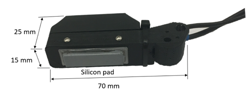
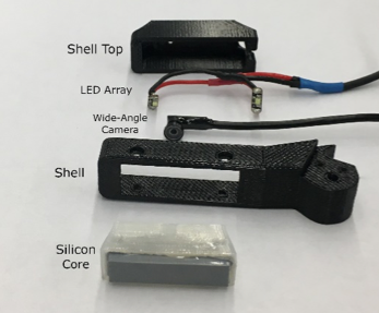
This sensor was designed to be adaptable to the Kinova KG-2 gripper. The modular design of thesensor allows it to be easily adapted to other grippers or applications as well by customizing the design of the shell, rather than designing a bulky adaptor add-on. The sensor also has a small form factor and low fabrication complexity, achieved by use of a wide-angle camera and omission of contact geometry measuring capabilities.
[1] S. Dong, W. Yuan, and E. Adelson, “Improved GelSight
Tactile Sensor for Measuring Geometry and Slip,” arXiv
preprint arXiv:1708.00922, 2017.
[2] E. Donlon, S. Dong, M. Liu, J. Li, E. Adelson, and A.
Rodriguez, “GelSlim: A High-Resolution, Compact, Robust, and
Calibrated Tactile-sensing Finger,” p. 9.
[3] Y. Zhang, Z. Kan, Y. A. Tse, Y. Yang, and M. Y. Wang,
“FingerVision Tactile Sensor Design and Slip Detection Using
Convolutional LSTM Network,” arXiv:1810.02653 [cs], Oct.
2018.
[4] Abdullah, “Object Exploration Using a Three-Axis Tactile
Sensing Information,” Journal of Computer Science, vol. 7, no.
4, pp. 499–504, Apr. 2011.
[5] A. Alspach, K. Hashimoto, N. Kuppuswamy, and R. Tedrake,
“Soft-bubble: A highly compliant dense geometry tactile sensor
for robot manipulation,” arXiv:1904.02252 [cs], Apr. 2019.
Sensor Fabrication
Source: https://github.com/geiman-uw/fingergelsight
Supplies
-
Chemicals
- Ease Release 200
- Silicones, Inc. XP-565
- Yellow Print-On Silicone Ink
- Print-On Silicone Ink diluent
- ?mm Transparent acrylic
- Gray Print-On Silicone Ink
- Acrylic glue
-
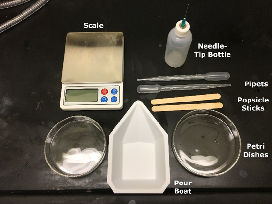
Accessories
- Glass Petri dishes (plastic ones will melt)
- Pour boats
- Popsicle mixing sticks
- Pipets
- Needle-tip bottle

-
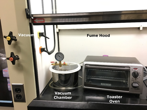
Equipment required
- Fume hood (if available)
- Vacuum chamber
- Toaster oven
- 3D printer
- Clear PLA 3D printer filament
- Laser cutter
-
Electronics
- Wide-Angle Camera
- 2 Adafruit LED Sequins
- Wires
- USB Cable
Core Procedure
You may find it most efficient to make 4-8 cores at a time with this procedure.
-
Prepare silicone
- Pour silicones, 10:1 base to activator by mass, in a pour boat. Use popsicle sticks to portion viscous materials like silicone base and inks, and pipets to portion less viscous materials like activator and dilutent.
- Mix using a popsicle stick. Never use the same pipet or popsicle stick for different materials.
Note: PLA parts shrink when exposed to heat. If you plan to modify the core, make your part approximately 5% bigger than the intended final size in order to account for this.
-
Cast silicone
- Spray petri dish with rubbing alcohol and wipe with Kimwipes to remove dust and debris.
- Spray petri dish with Ease Release 200.
- Mix 17-18g XP-565, then pour 15g into dish. Amount may vary depending on desired thickness and petri dish size.
- Vacuum until no bubbles remain. Several release and vacuum cycles helps to accelerate process.
- Heat petri dish on warm (175 °F) in toaster oven for 10 min to cure silicone.
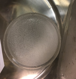
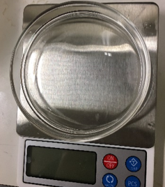
Mixing silicone introduces air bubbles (left) which are removed by placing in vacuum chamber
-
Add yellow layer
- Starting with a 1g of yellow Silicone Ink, mix in a 1:10:60 activator:ink:diluent ratio. The resulting mixture should be approximately the consistency of chocolate milk.
- Pour in a thin even layer over the XP-565 petri dish. The layer should be as thin as possible, so you will not use all of the yellow silicone. Heat the dish on warm for 15 min to cure.
-
3D printer
- All production files can be found in finger_gelsight_production.
- Print gelsight_shell.stl and gelsight_piece.stl in opaque PLA.
- Print gelsight_corefilled_103.stl open side up in clear PLA with 0.2mm layer height, raft, and no support.
-
Laser Cutter
- From acrylic, laser cut gelsight_corefilled_acrylic.stl with vector set to 8s 100p 100f.
- Remove silicone with yellow layer from petri dish and place yellow-side up in laser cutter. Laser cut gelsight_gelpattern_5x14.ai with raster set to 11s 4p 50f and vector set to 5s 75p 50f.
-
Cast transparent core silicone: Mix enough XP-565 to fill the prepared cores, and vacuum in pour boat until most bubbles are gone.
-
Glue acrylic into core: Using a needle-tip bottle, apply acrylic glue to the inside of the cores and place acrylic. Make sure the glue gets all the way around the edges, otherwise the silicone will seep past the acrylic and obstruct the camera lens later.
-
Fill core with silicone: Carefully fill each core with silicone (at or below edge; do not overflow) and vacuum until no bubbles remain, then heat on warm for 5 min.
-
Add protection layer: Starting with 0.5g of gray Silicone Ink, mix in a 1:10:40 activator:ink:diluent ratio. The resulting mixture should be somewhat thicker than chocolate milk. Cover the bottom of each cut-out gel with electrical tape, making sure there are no bubbles where gray silicone could seep under the gel. Place dot-side up in a petri dish. Using a pipet, cover each gel in gray silicone mix, making sure all untaped sides are covered.
-
Attach gel to core: Once cores have cooled, spread a thin layer of mixed XP-565 on each core. Gently place gel on XP-565 layer, being careful to avoid introducing bubbles. Heat on warm for 5 min.
Electronics procedure
Wire two Adafruit LED sequins in parallel. Cut and strip a USB cable and solder each LED lead to the appropriate USB cable wire.
Assembly and installation
- Tap core and shell holes with M2 tap.
- Attach LEDs to core with transperent double sided tape.
- Screw core into shell.
- Attach camera to core with double sided tape, being careful not to force the lens into the hole.
- Tape wires to shell to provide more stability.
Congratulations, your Gelsight-mini tactile sensor is ready to be used. Use the dot tracking package available at https://github.com/GelSight/tracking for readings from the sensor.