

Overview
This page provides detailed instructions on how to build the hardware for the robot-assisted feeding system presented in the HRI'25 paper "Lessons Learned from Designing and Evaluating a Robot-Assisted Feeding System for Out-of-Lab Use." Note that multiple components are custom-designed for the hardware we are using, some of which may be outdated or discontinued. As such, these instructions are NOT intended to be replicated exactly, but rather to serve as a starting point and guide for building a similar system.
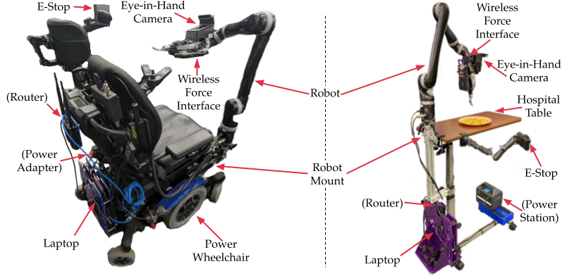
Table of Contents
1. Base Hardware
The system uses the following base hardware components:
- Robot: Kinova® Jaco® (Gen2) Robot Arm, 2-finger gripper
- RGB-D Camera: Intel Realsense D415
- Force-Torque Sensor: ATI Nano25 6-DoF F/T sensor and Wireless F/T transmitter (discontinued)
- Main Compute: Lenovo Legion 5 15IAH7H (i7-12700H CPU, Nvidia RTX 3060 6GB GPU, 16GB RAM, 1TB SSD)
- Eye-in-Hand Compute: NVIDIA Jetson Nano
- E-Stop Button: egg switch accessibility button (3.5mm TS jack) and corresponding USB audio adapter
-
Networking:
-
Option A ("on-board network"):
Cradlepoint IBR900
(discontinued)
- Note: a key benefit of this router is its Wifi as WAN capability, which improves system portability.
- Option B ("home network"): TP-Link Archer C9 v3.0
-
Option A ("on-board network"):
Cradlepoint IBR900
(discontinued)
- Power (Optional): Anker 521 300W Portable Power Station
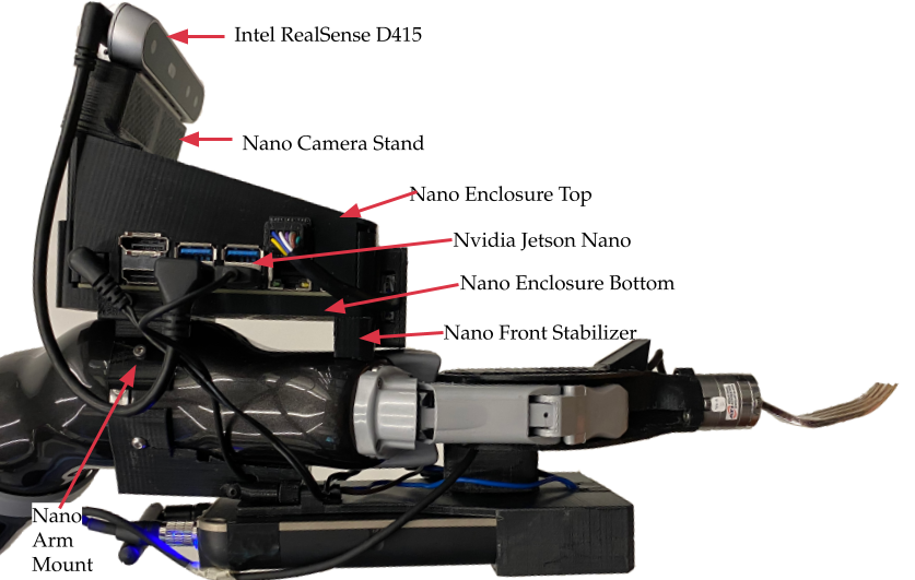
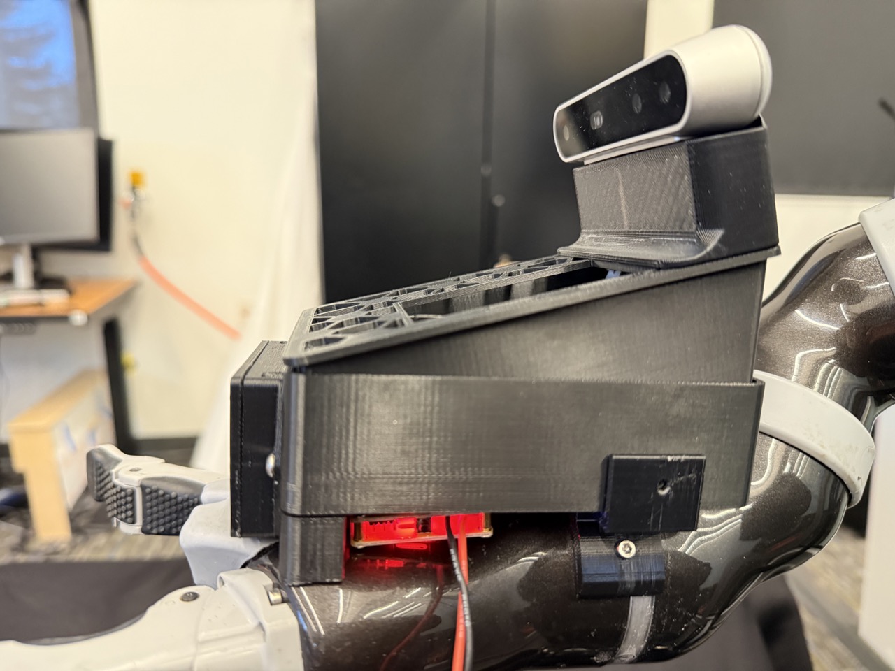
2. Eye-in-Hand System
The eye-in-hand system mounts an RGB-D camera and compute after the 6th joint of the robot arm, providing a fixed transform between the camera and the fork.
2.1 Parts List
- Intel Realsense D415
- Nvidia Jetson Nano
- 3D Printed Parts (printed with PLA):
- M3 screw kit: 10 M3 10mm screws, 2 M3 6mm screws, 6 M3 nuts
2.2 Building the Eye-in-Hand System
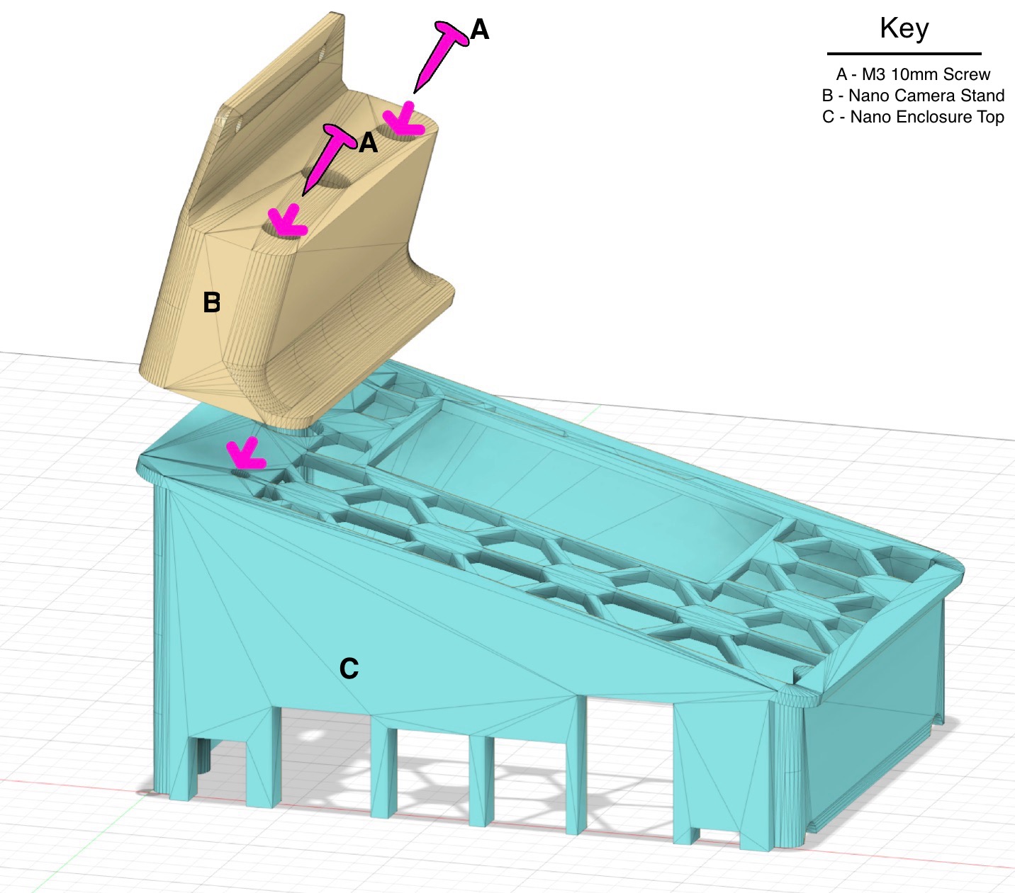
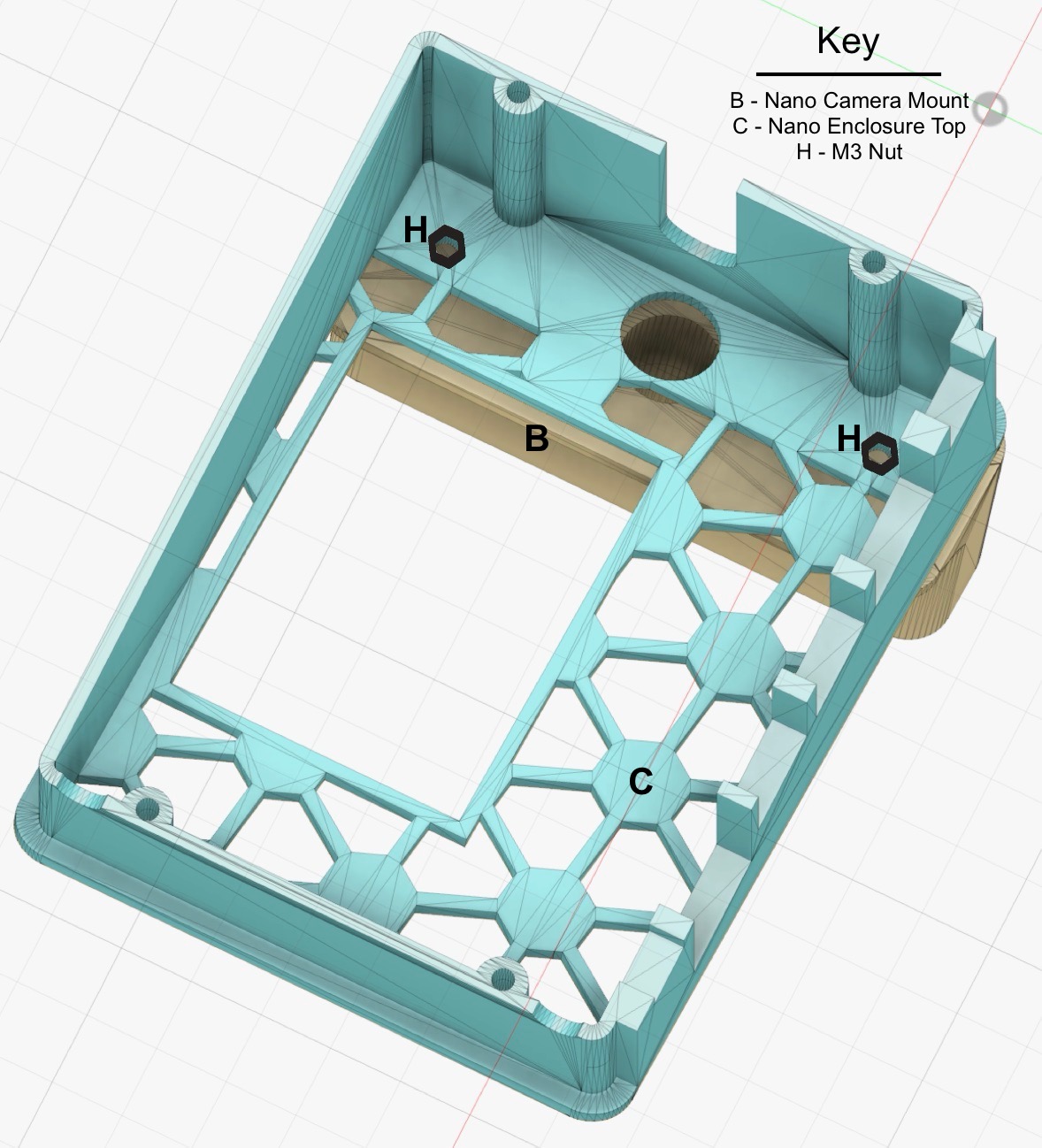
Step 1
Attach Nano Camera Stand to Nano Enclosure Top with two M3 10mm screws and two M3 nuts.
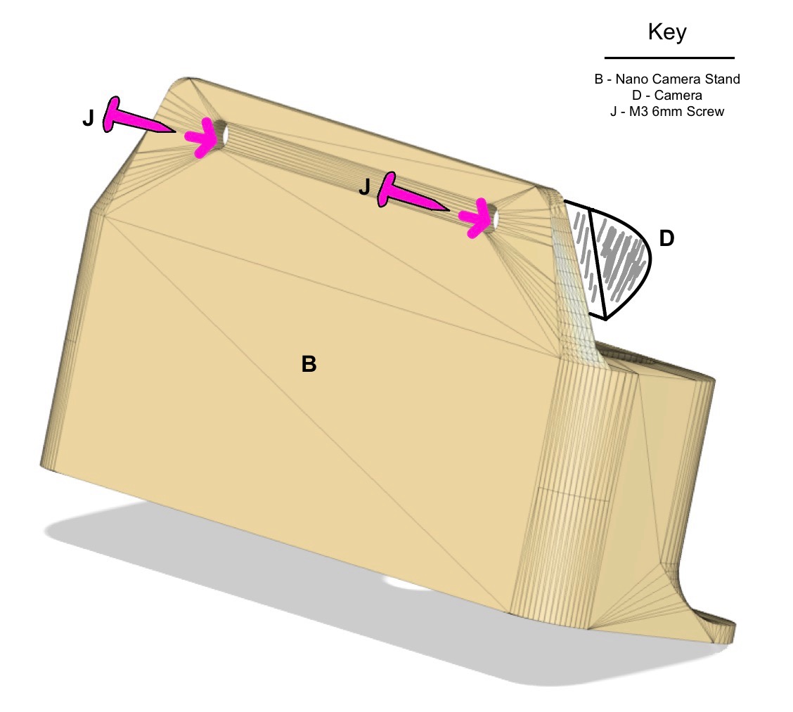
Step 2
Attach the camera to the Nano Camera Stand with two M3 6mm screws.
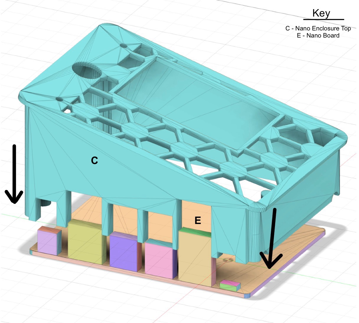
Step 3
Slide the Jetson Nano board into the Nano Enclosure Top, from below.
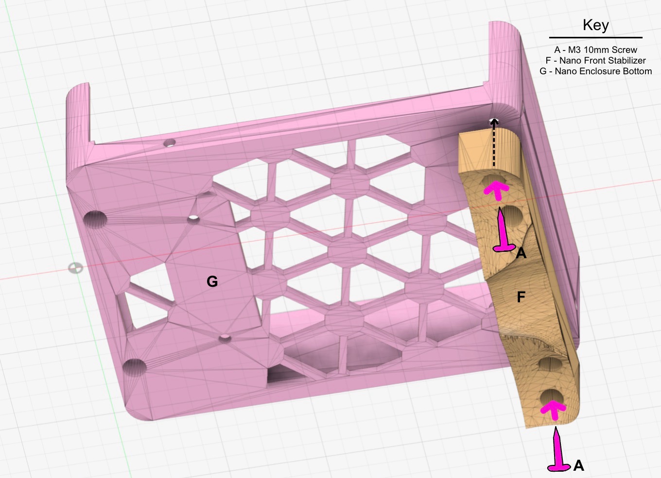
Step 4
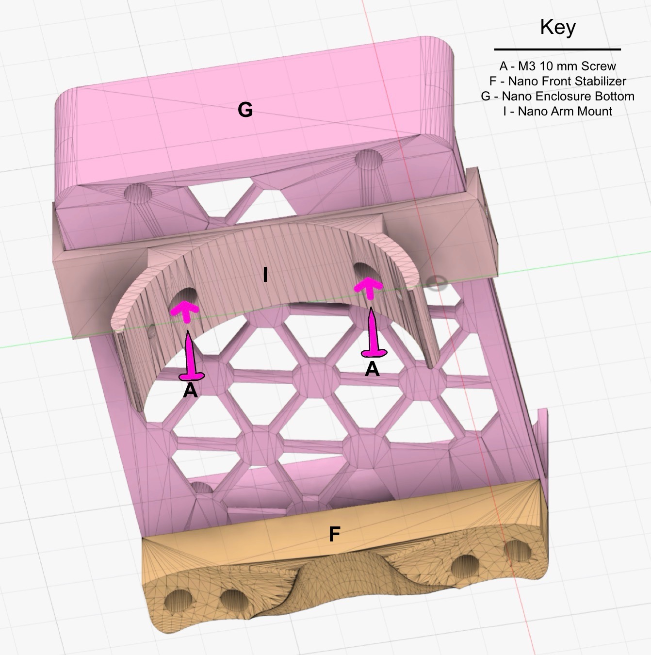
Attach the Nano Front Stabilizer to the Nano Enclosure Bottom with two M3 10mm screws and two nuts.
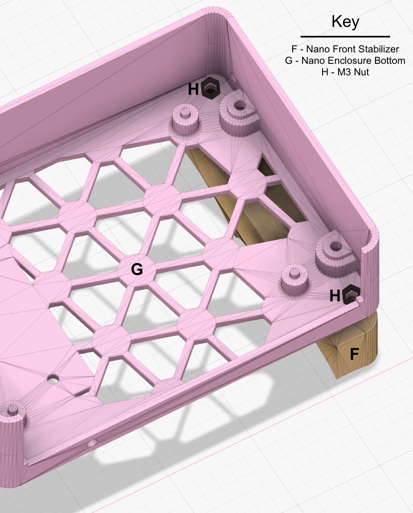
Step 5
Attach the Nano Arm Mount to the Nano Enclosure Bottom with two M3 10mm screws and two nuts.
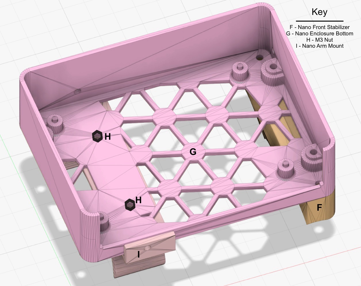
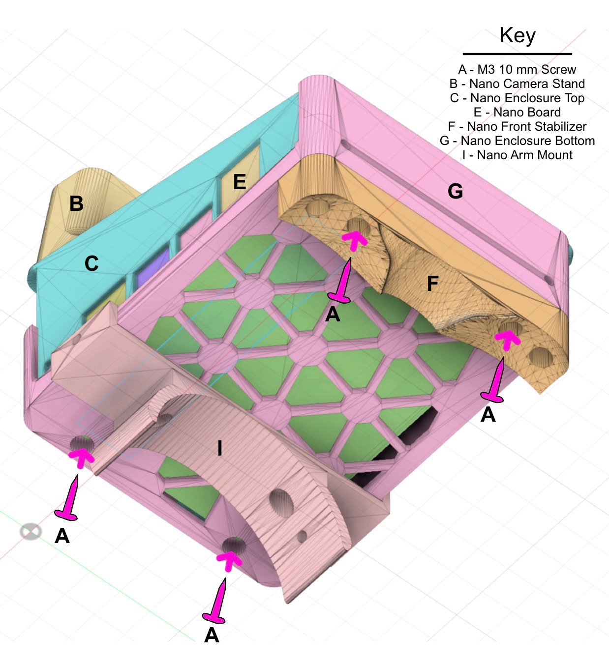
Step 6
Attach the Nano Enclosure Bottom to the Nano Enclosure Top with four M3 10mm screws. Note that there are small raised cylindrical "posts" on the inside of the enclosure bottom (see image in Step 5) that the Jetson Nano slides into. It may be helpful to slide the Nano out from enclosure top, rest it on the cylindrical "posts", and then slide the enclosure top down onto it.
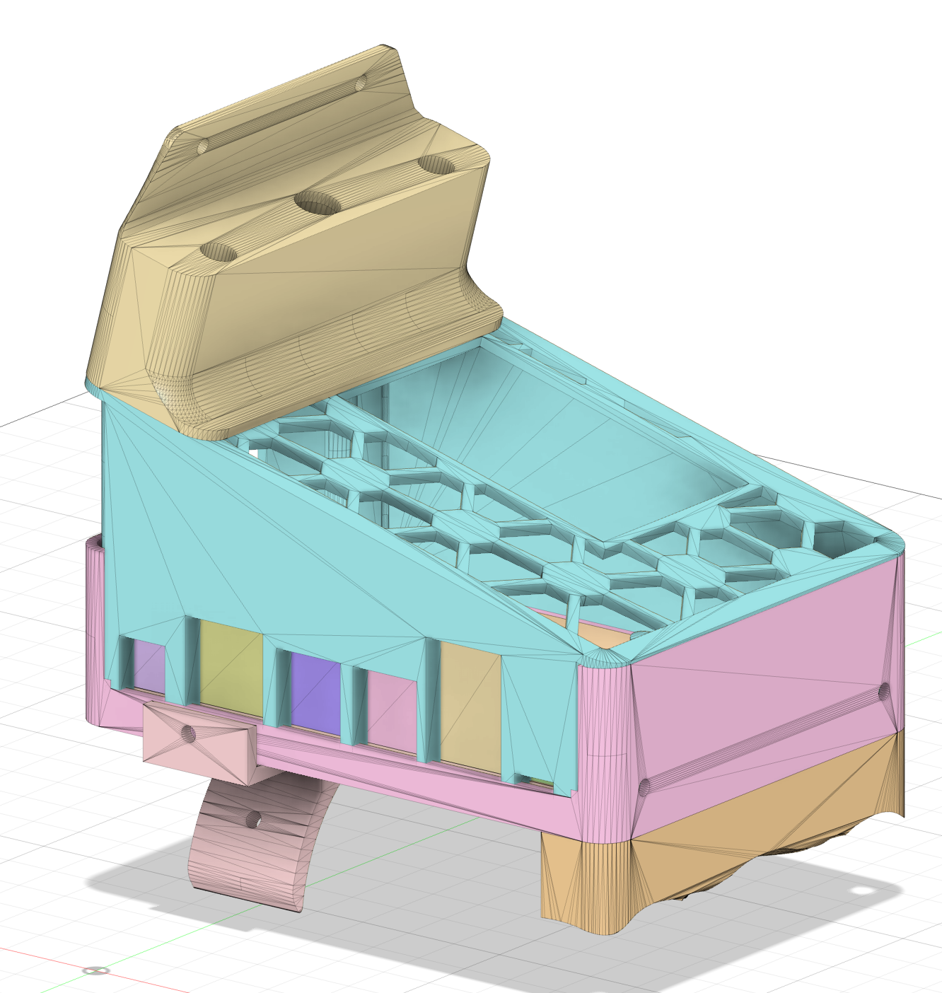
Step 7
Congratulations! You have successfully built the eye-in-hand system.
2.3 Attaching the Eye-in-Hand System to the Robot Arm
Step 8
Remove the gray plastic cover from the robot arm's 6th joint.
Step 9
Home the robot. On the 6th joint, one screw should point straight up. Unscrew the screws to the left and right of that screw.
Step 10
Screw the arm mount into the two now-empty screw holes on the 6th joint, using 12mm M3 screws. Congratulations, you have successfully attached the eye-in-hand system to the robot arm!
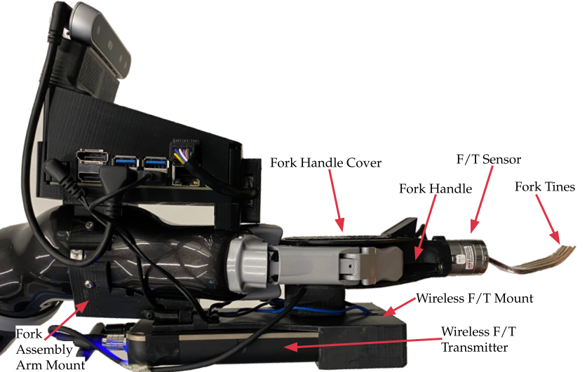
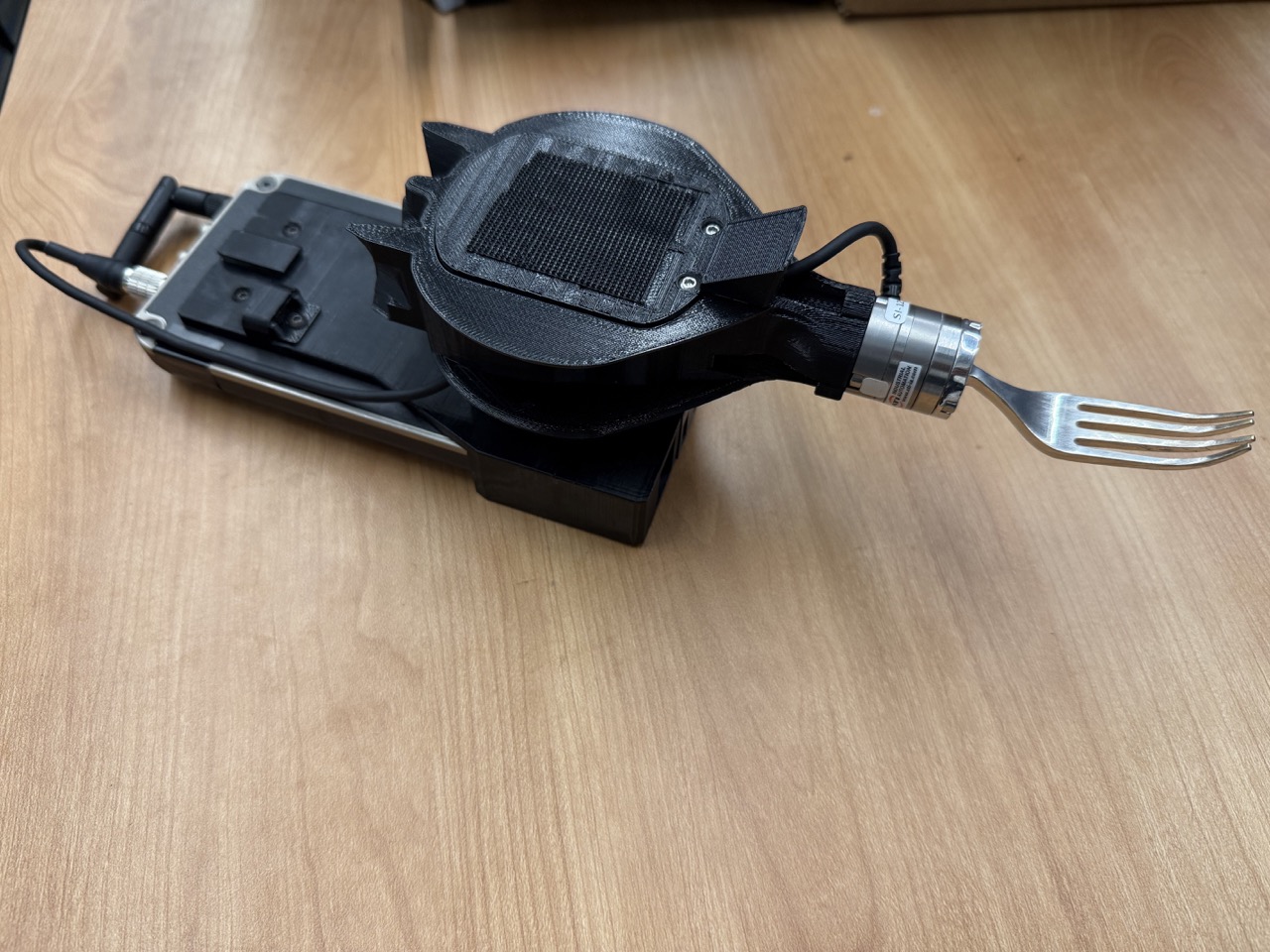
3. Fork Assembly
The fork assembly consists of 3D printed components that allow the robot's two-finger gripper to hold onto a fork, with a force-torque (F/T) sensor and wireless F/T transmitter attached.
3.1 Parts List
- ATI Nano25 6-DoF F/T sensor
- Wireless F/T transmitter (discontinued) with a small antenna
- 3D Printed Parts (printed with PLA):
- Fork Tines (3D printed with metal):
- M3 screws and nuts (e.g., here and here): three 4mm, seven 6mm, seven 8mm, one 12mm, one 16mm, two 30mm, & four nuts
3.2 Building the Fork Assembly
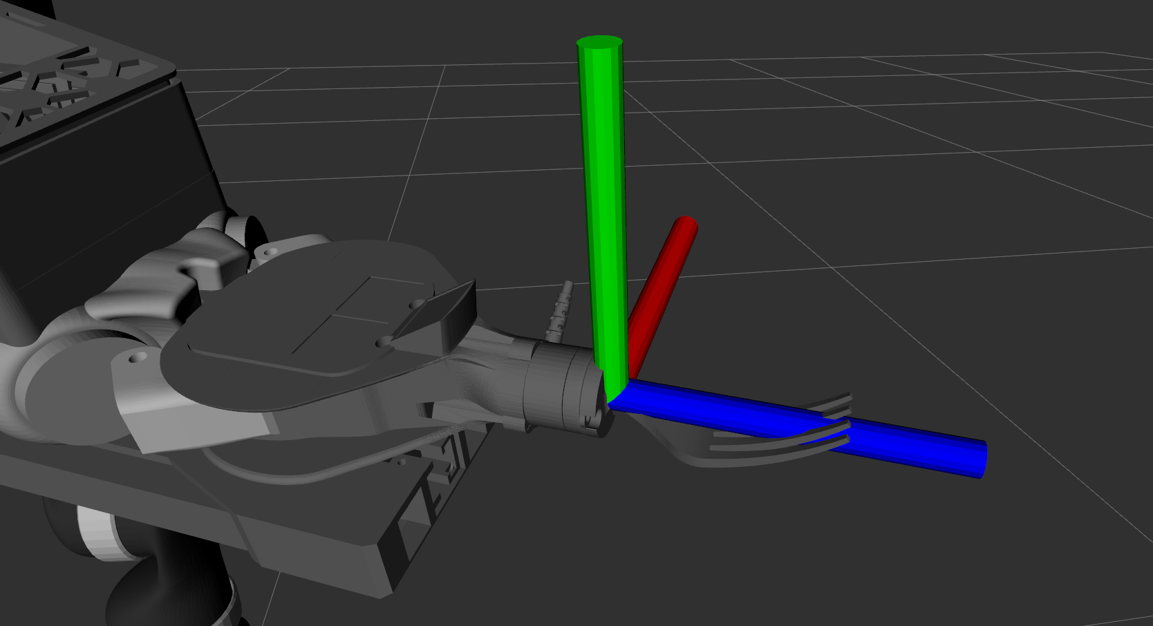
Step 1
Identify the +x (red), +y (green), and +z (blue) directions of the F/T sensor. Attach the forktines to the F/T sensor with three M3 4mm screws, such that if you're looking down the fork handle to the fork tines, +x goes to your left, +y goes up, and +z goes away from you (from handle top to fork tip).
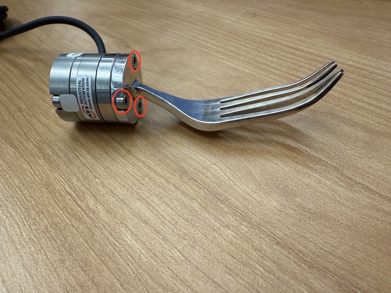
Step 2
Attach the fork handle to the F/T sensor using three M3 8mm screws.
Step 3
Insert three M3 nuts into the hexagonal slots on the inside of the wireless F/T mount.
Step 4
Attach the mag cover and switch cover to the wireless F/T mount using three M3 6mm screws. Note that these elements are optional, and only necessary for wireless magnetic charging of the F/T transmitter.
Step 5
Attach the wireless F/T transmitter to the wireless F/T mount with four M3 6mm screws.
Step 6
Run the F/T sensor wire through the hole in the fork handle. Attach the fork handle to the wireless F/T mount using two M3 30mm screws.
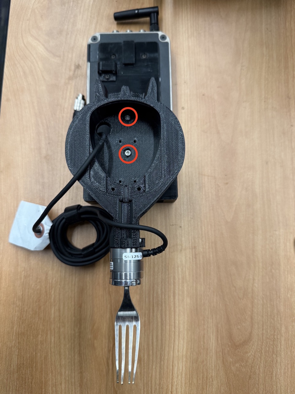
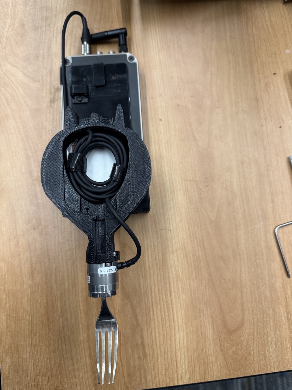
Step 7
Arrange the remaining excess wire in the hollow of the fork handle. To ensure the right amount of excess wire is left, consider plugging it into the F/T transmitter.
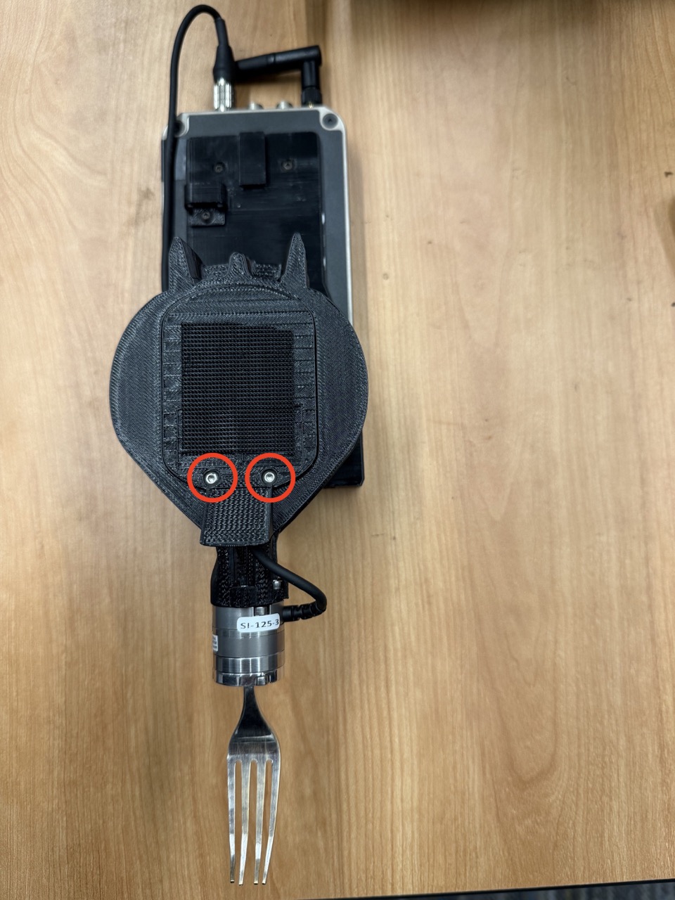
Step 8
Attach the fork handle cover to the fork handle using two M3 8mm screws.
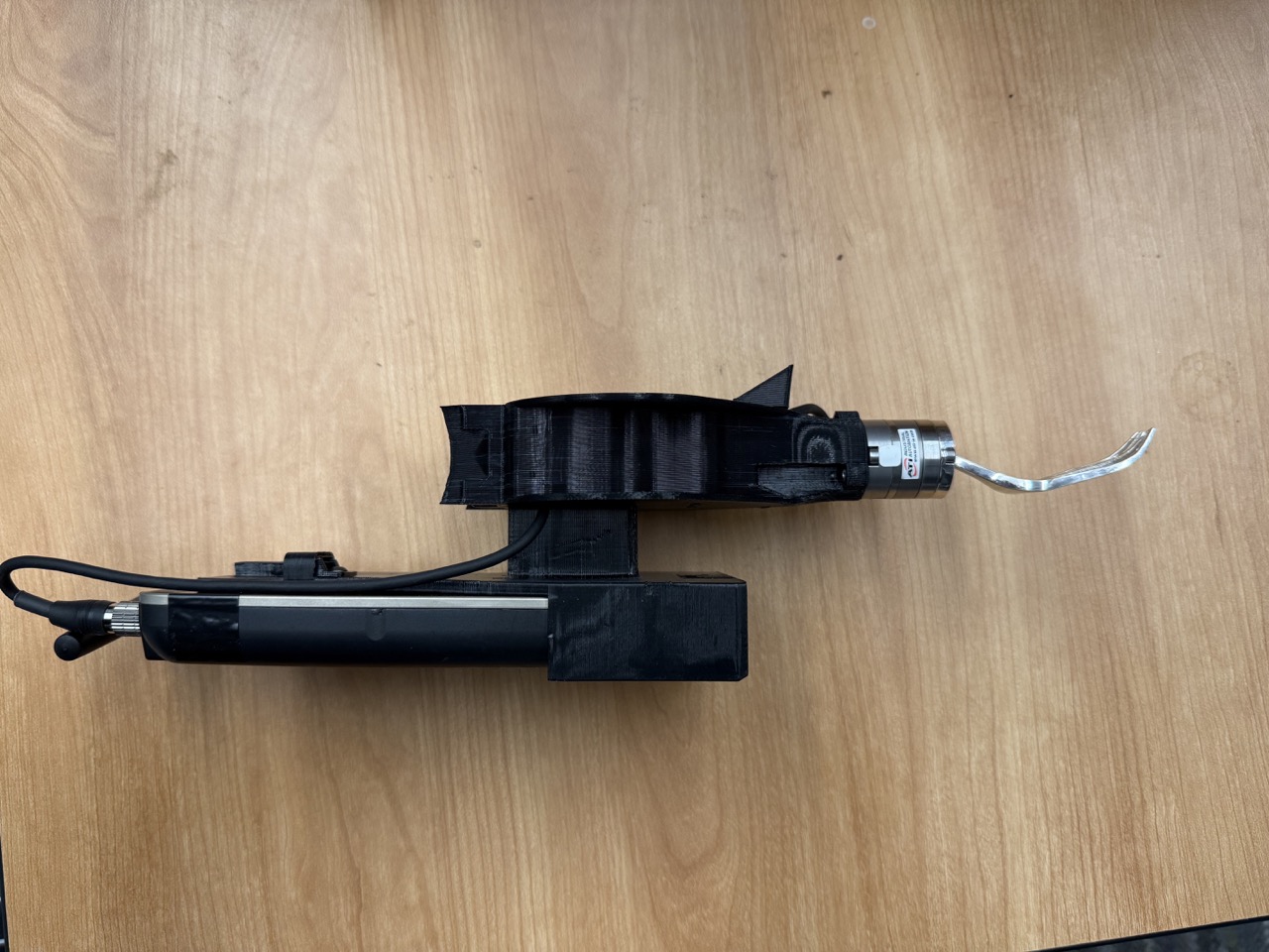
Step 9
Congratualtions! You have successfully built the fork assembly.
3.3 Attaching the Fork Assembly to the Robot Arm
Step 10
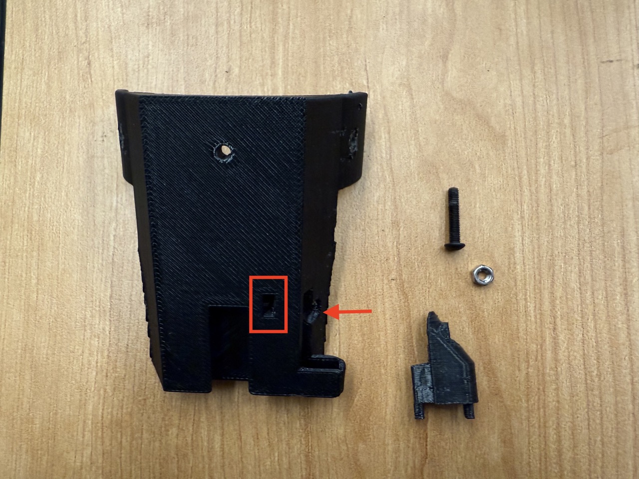
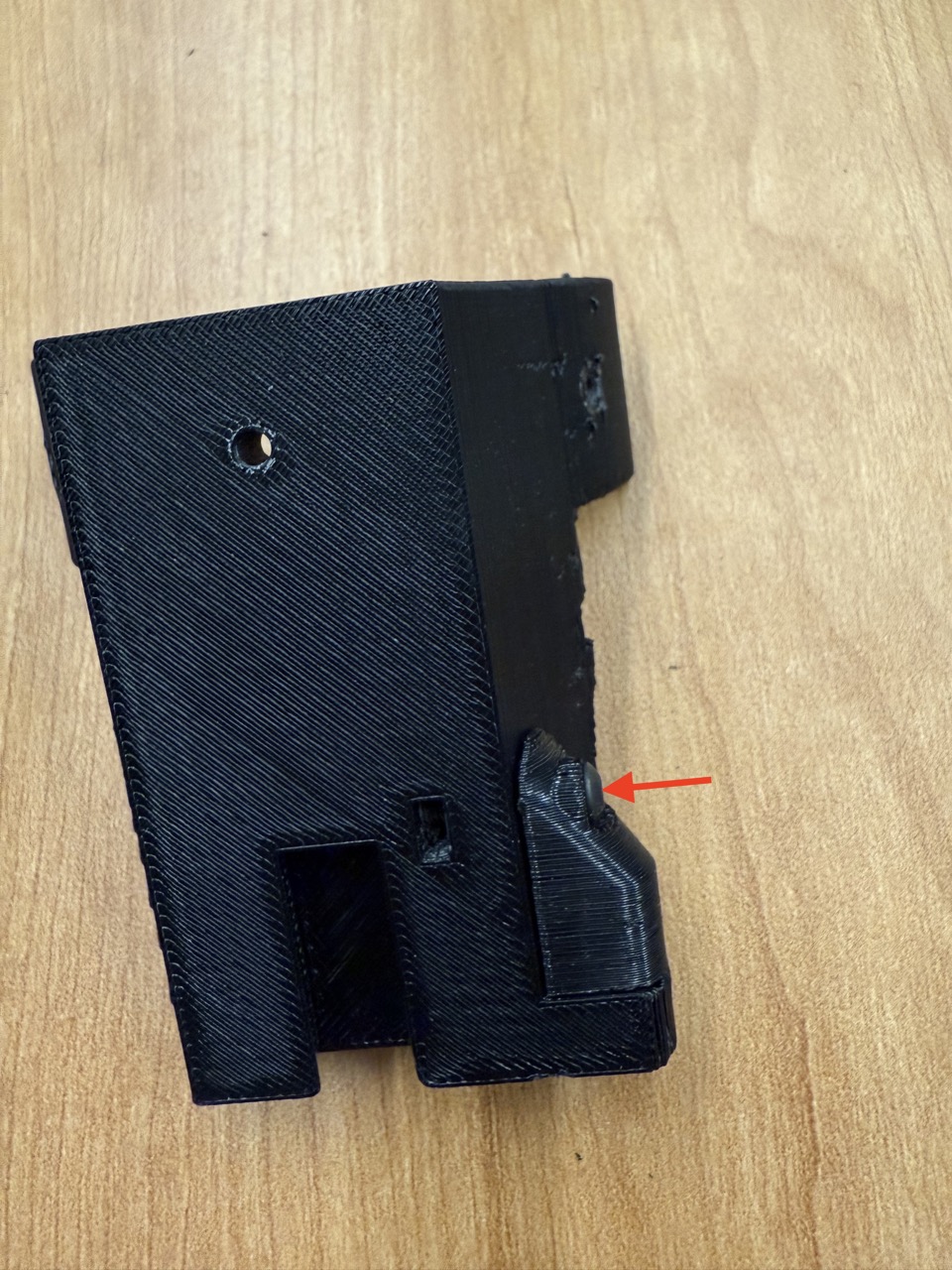
Insert an M3 nut into the slot at the bottom of the arm mount (if the nut cannot fit due to 3D printer support material, it is fine to continue without the nut). Attach the arm mount mag cover to that spot using one M3 16mm screw. Note that this step is optional, and only necessary for wireless magnetic charging of the F/T transmitter.
Step 11
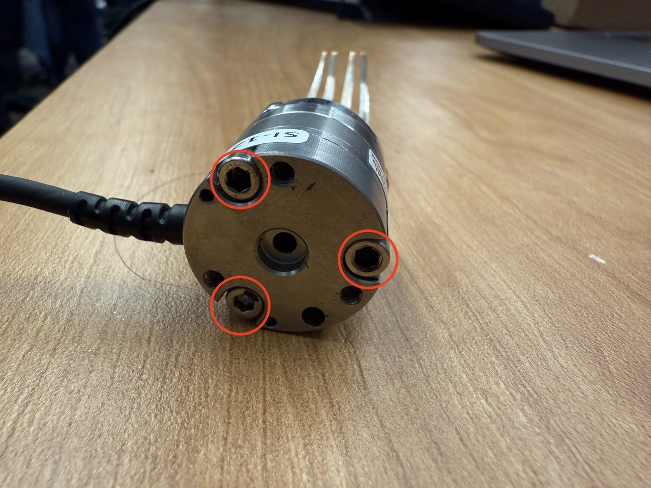
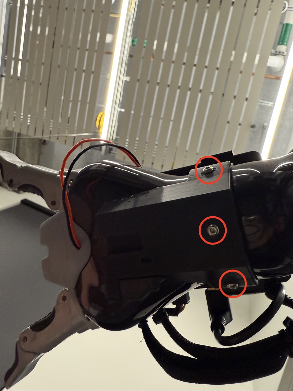
Home the robot. On the 6th joint, one screw should point straight down. Unscrew that screw and the the screws to its left and right.
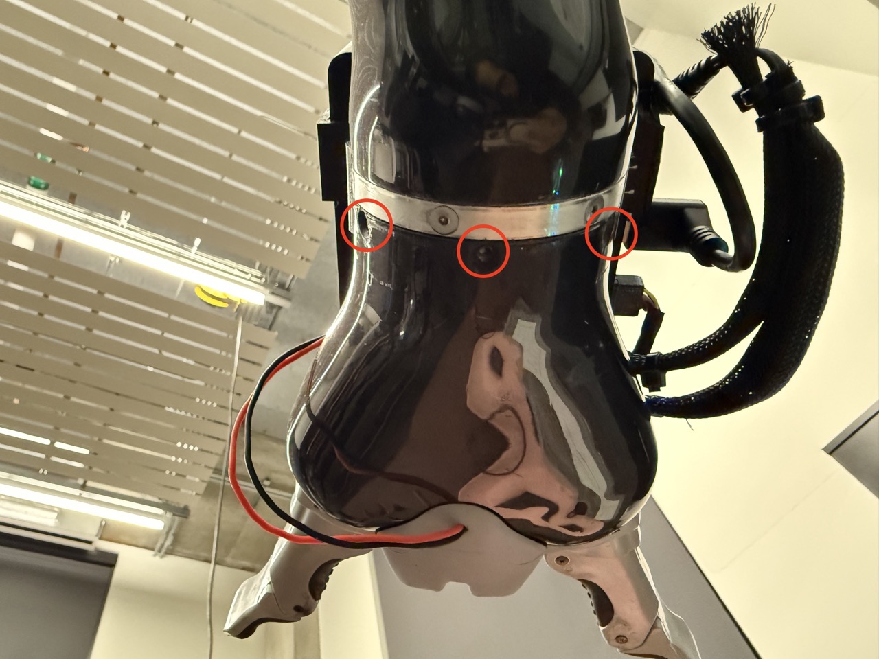
Step 12
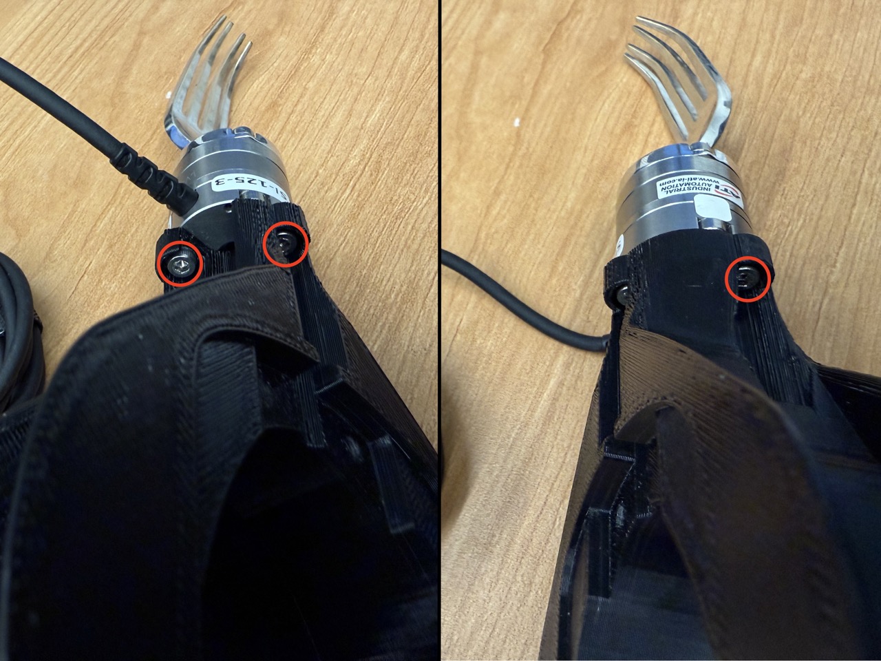
Screw the arm mount into the three now-empty screw holes on the 6th joint, using one M3 12mm screw (center) and two M3 8mm screws (sides).
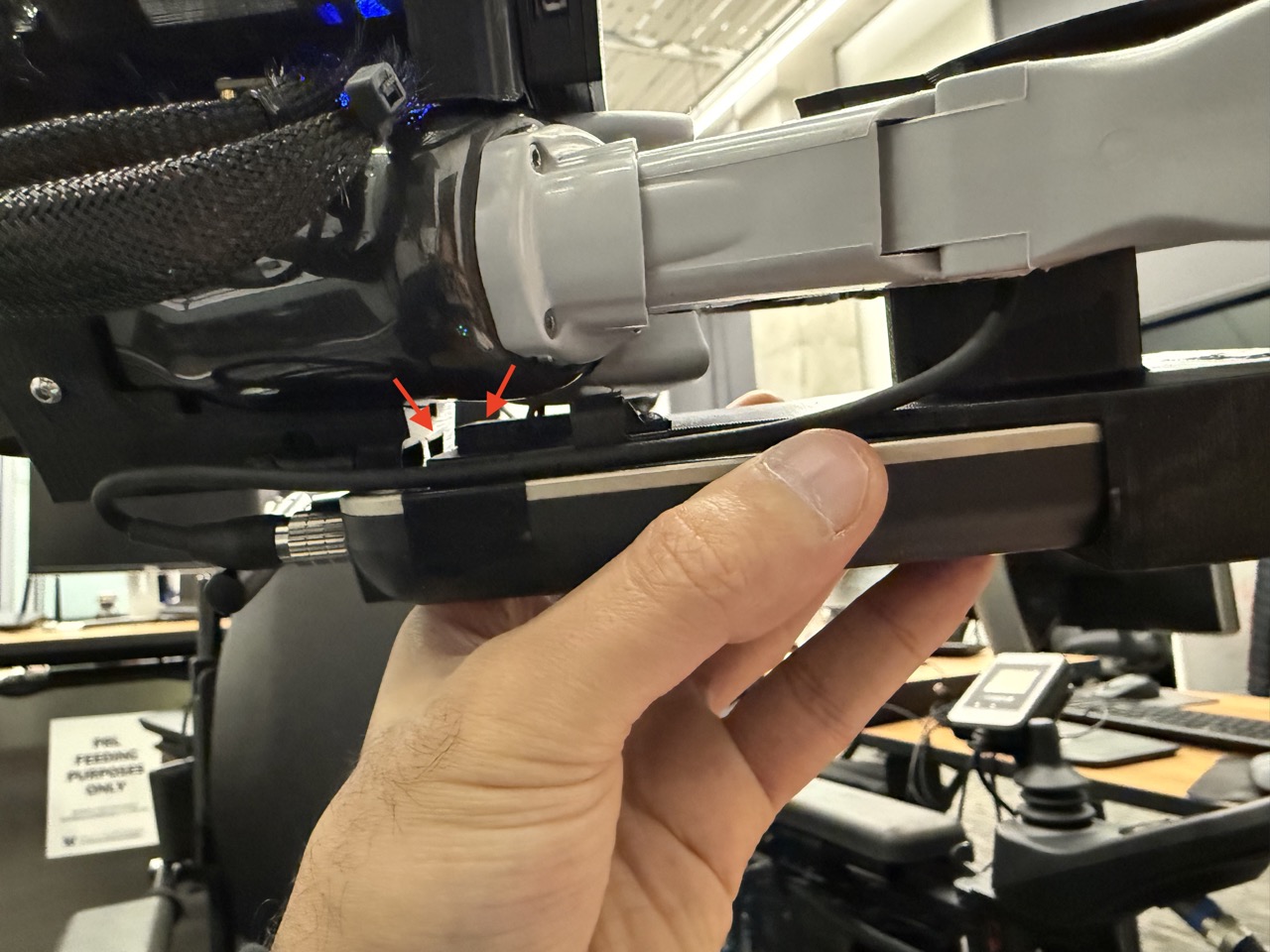
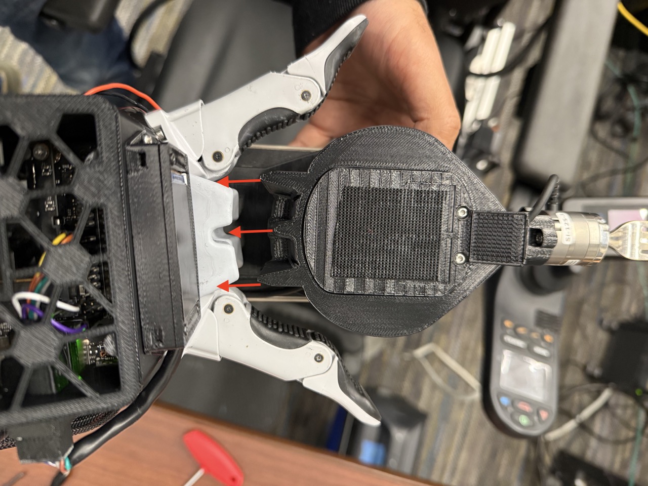
Step 13
Open the gripper. Slide the fork assembly into the gripper. Ensure the trapezoidal extrusion on the wireless F/T mount slides into the arm mount's corresponding trapezoidal slot (this is intentionally a tight fit). Further ensure that the extrusions at the top of the fork handle slide into the corresponding slots in the gripper. Close the gripper.
Step 14
Congratualtions! You have successfully attached the fork assembly to the robot arm.
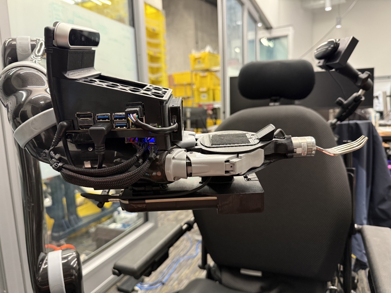
4. System Mounts
Our system has two main mounts: (a) the robot mount, which attaches the robot arm to the system's base (e.g., wheelchair or hospital table); and (b) the electronics mount, which contains the laptop, optional router, and optional power supply.
4.1 Robot Mount
For mounting, the Kinova® Jaco® arm can be screwed onto any piece of 40-40. As such, the basic elements of any mount for the robot include: (a) T-slotted 40-40 aluminum extrusions; (b) M8 40-40 T-slot bolts; and (c) M8 clamping lever ratcheted screws. We recommend avoiding 40-40 lite, as the few-millimeter size difference can result in a loose robot mount. Using the building blocks listed above, we developed three different mounts for the robot arm: (a) a wheelchair mount; (b) a hospital table mount; and (c) a tripod mount.
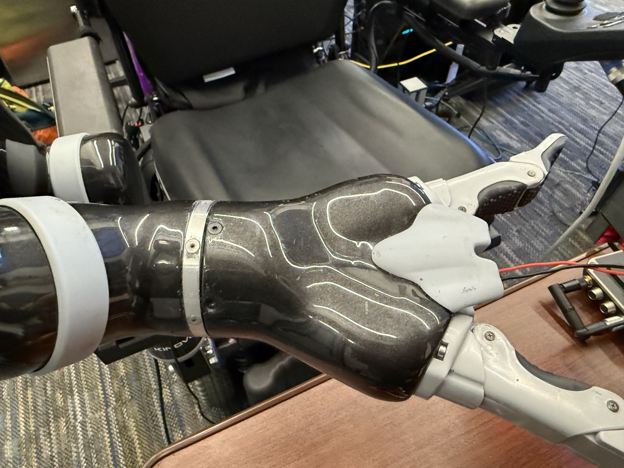
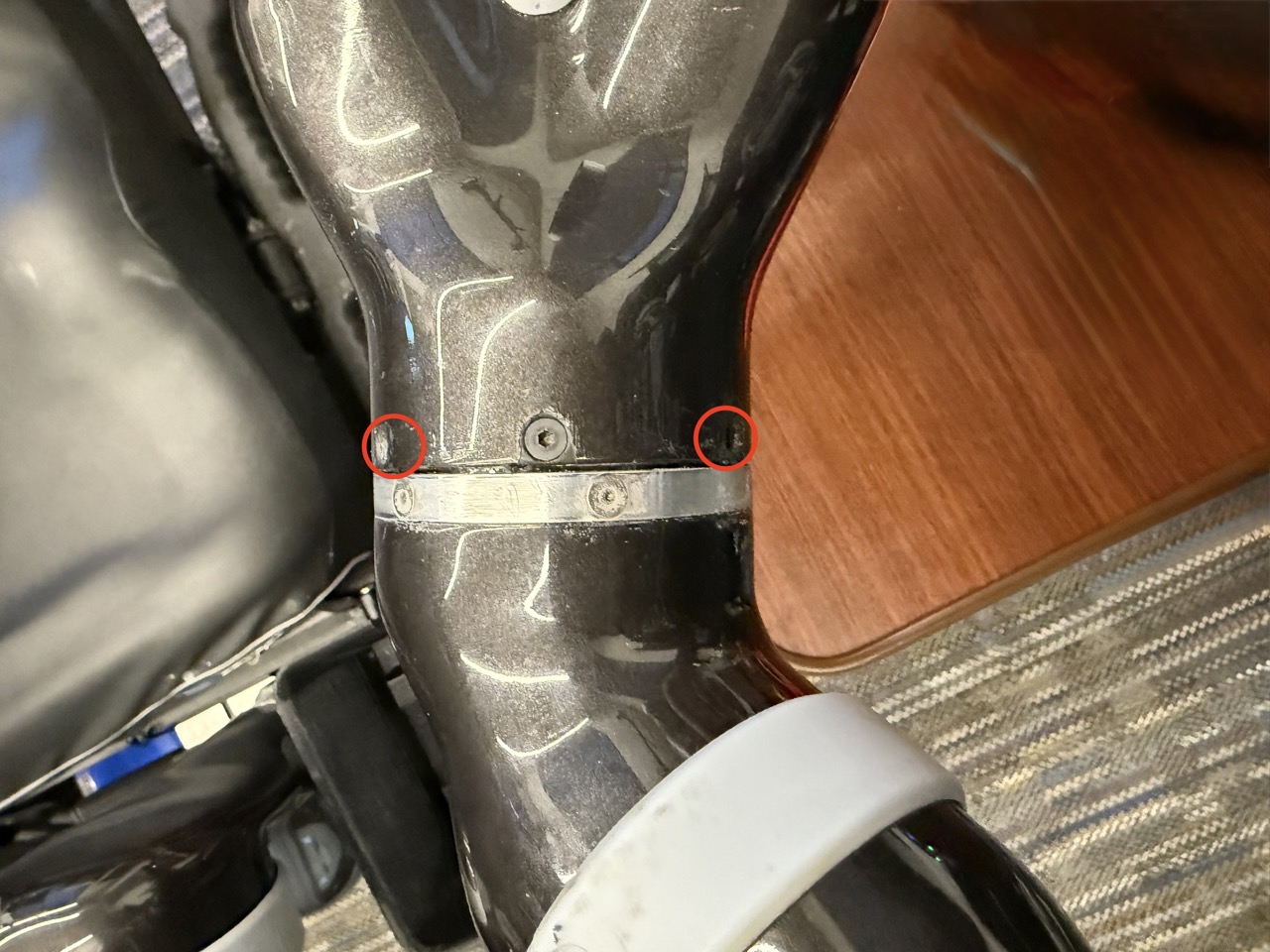
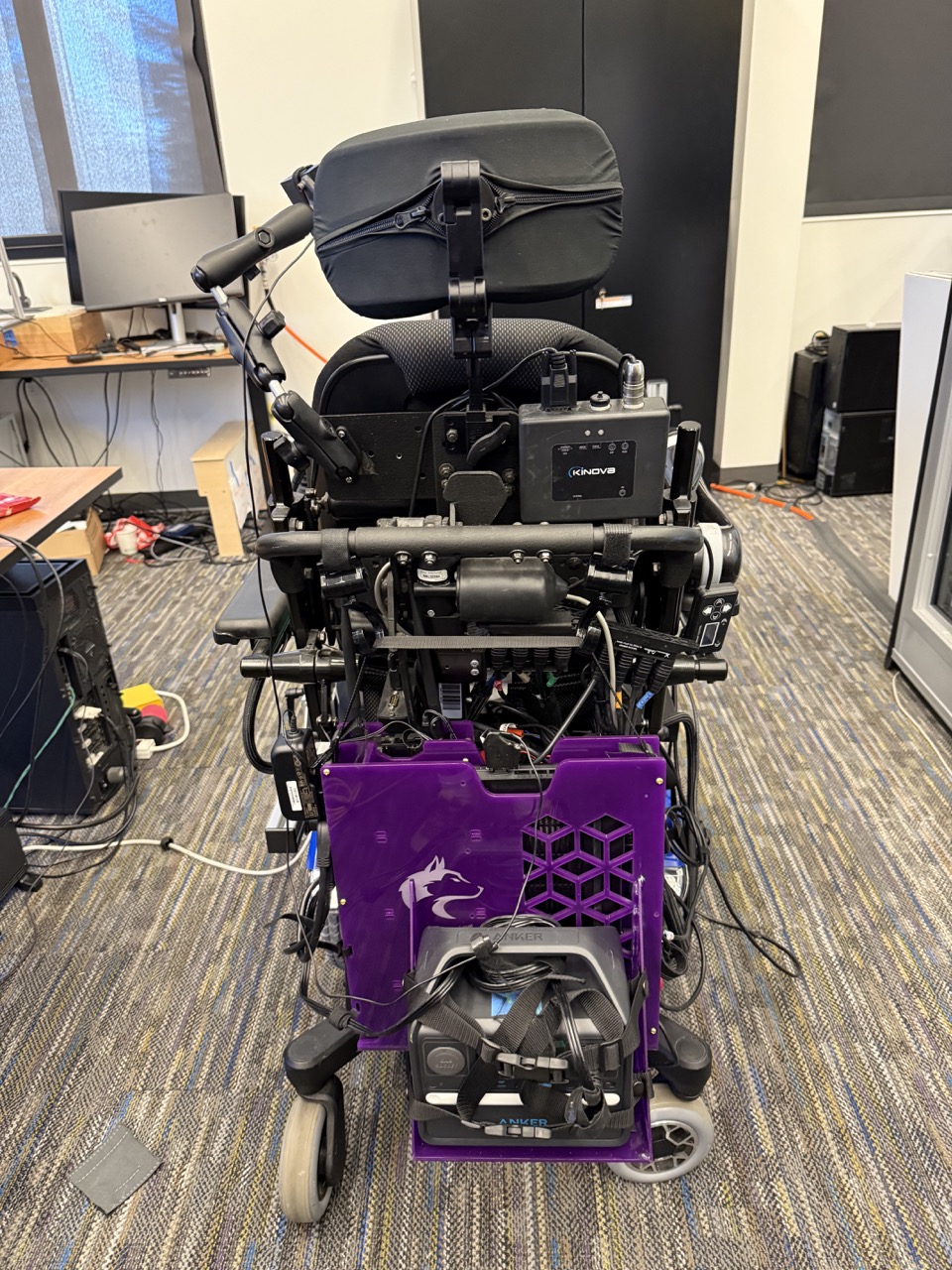
4.1.1 Wheelchair Mount
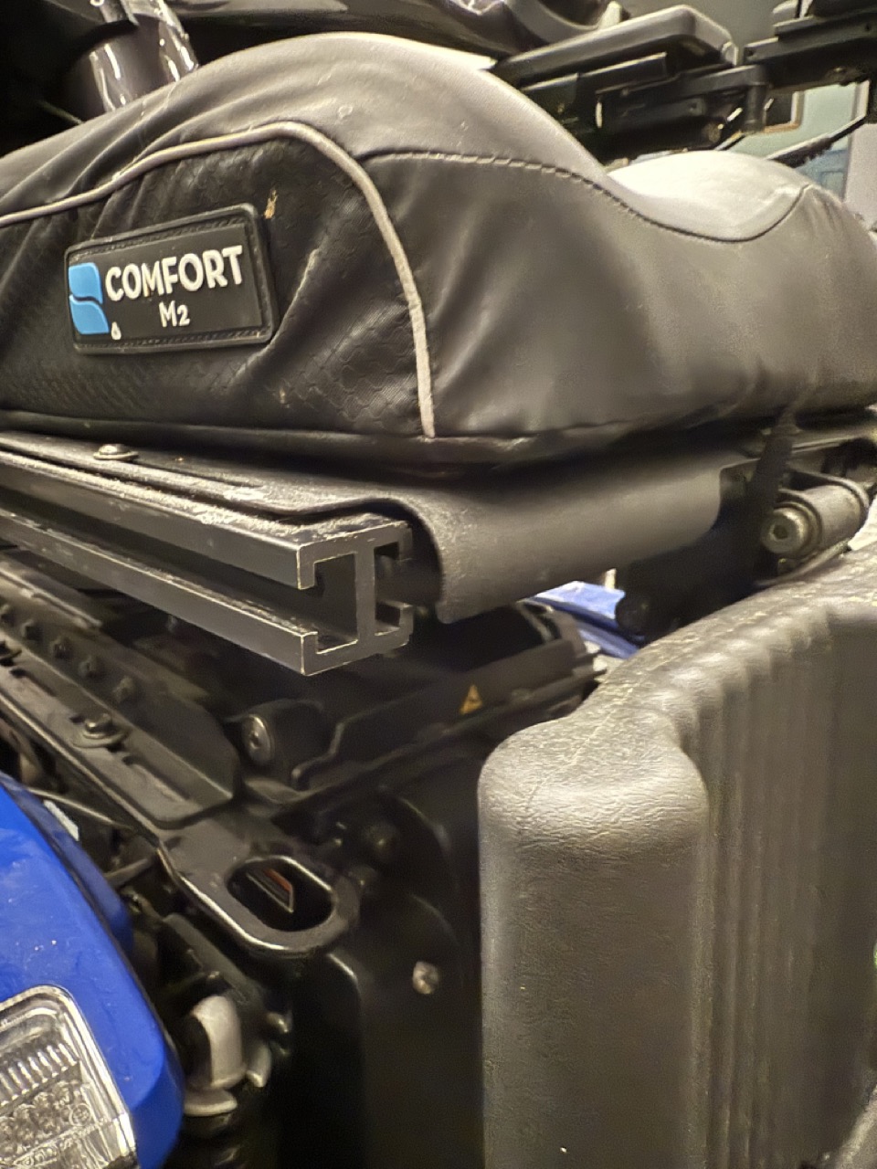
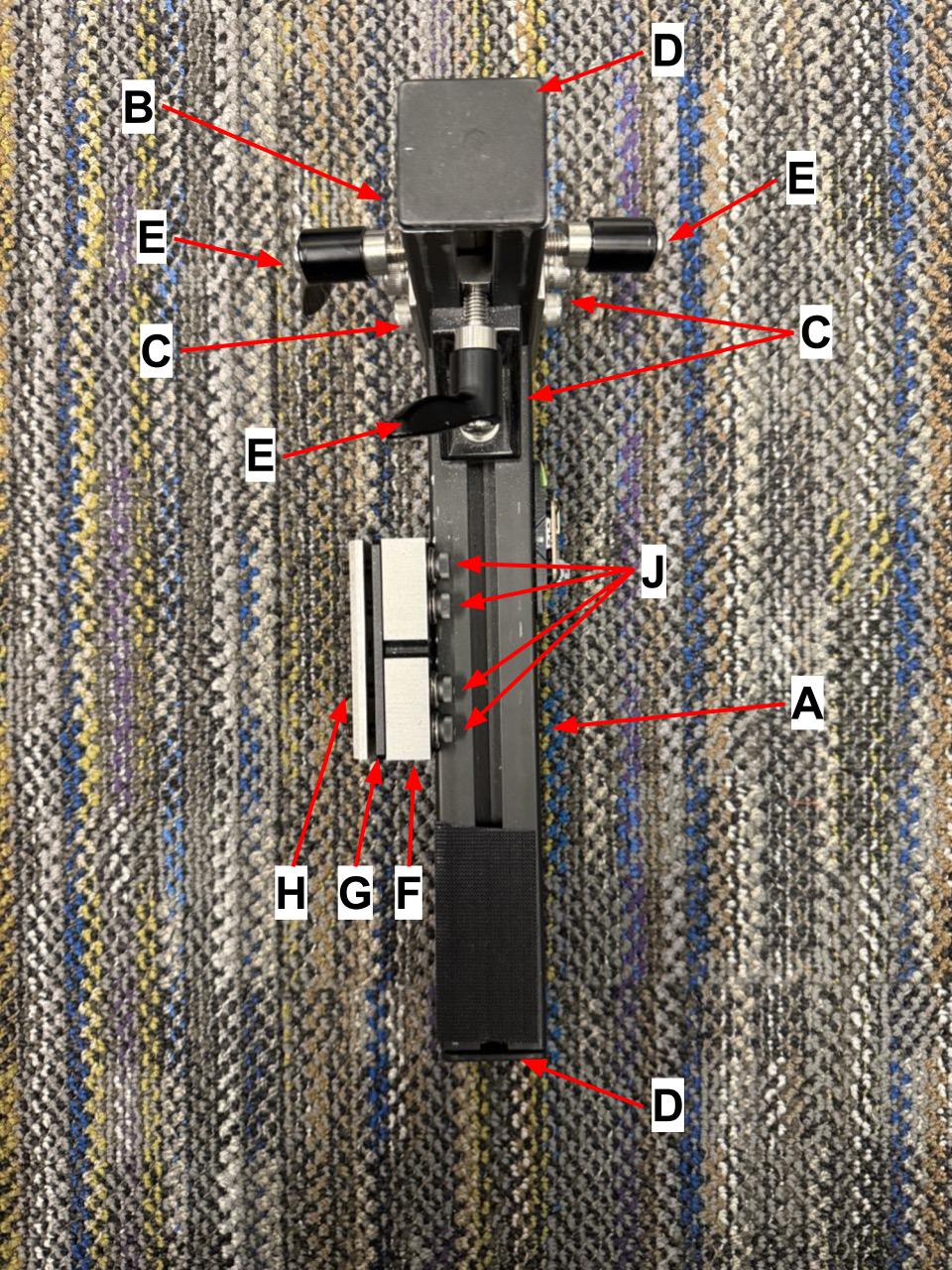
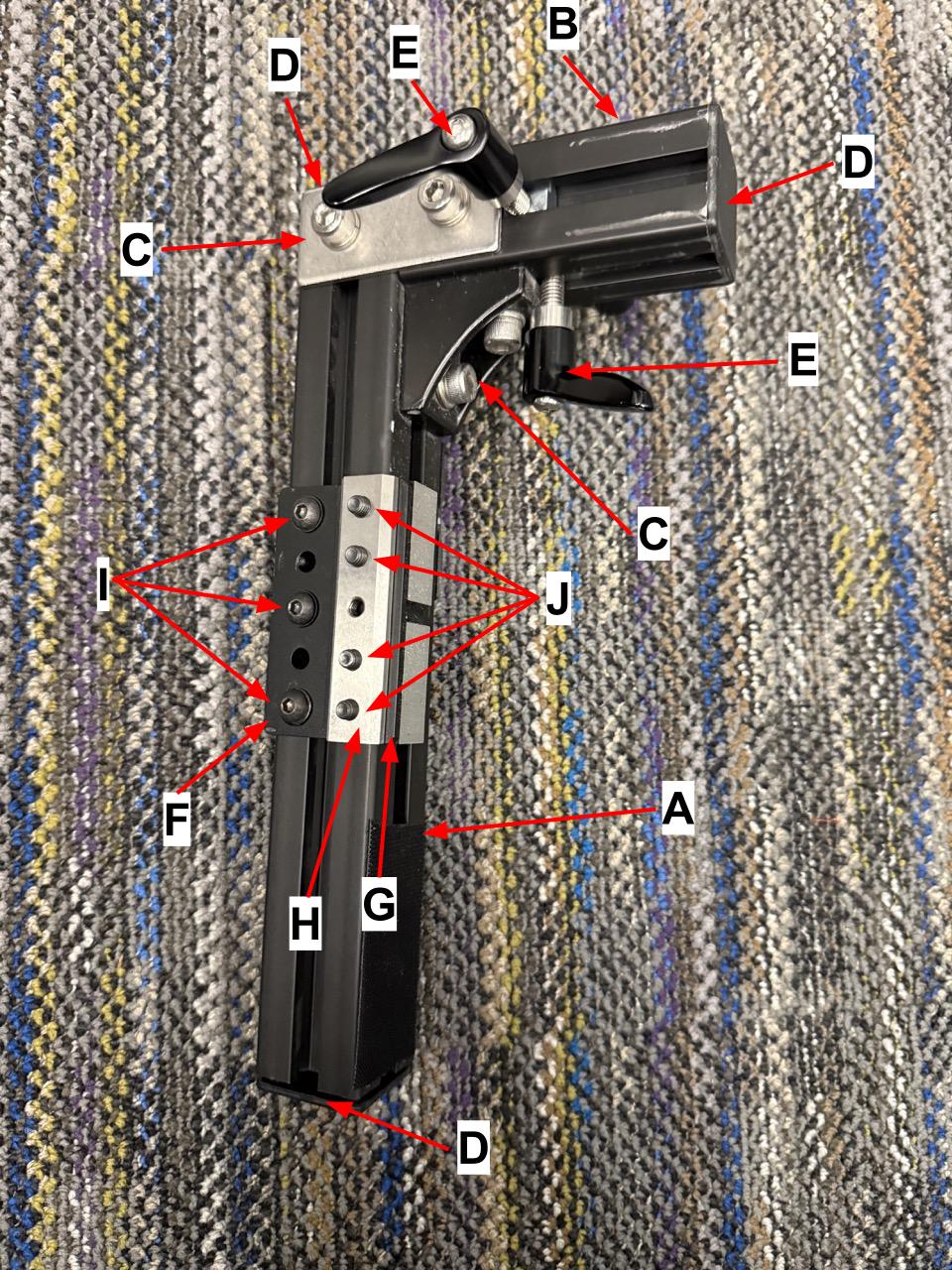
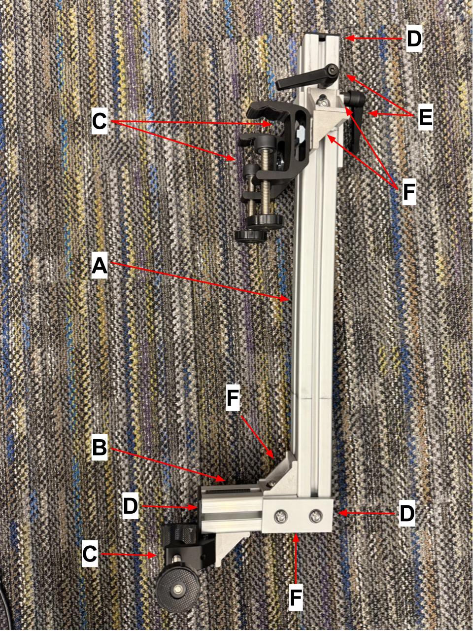
Power wheelchairs tend to have a sliding track below the seat, on both sides, which can be used to attach accessories (ours is 9mm x 16mm internal dimensions on each half of the track; see pic). We leverage that sliding track for our wheelchair mount, which consists of the following parts (labeled in the images):
- A 30cm piece of 40-40
- A 10cm piece of 40-40
- Two joining plates, a corner bracket, and associated M8 screws and nuts
- Three 40-40 end caps
- Three clamping lever ratcheted screws
- A thick custom-designed aluminum spacer block (5cm x 8cm x 1.5cm), with five evenly spaced unthreaded holes to accomodate M6 screws.
- A thin custom-designed aluminum spacer block (2.5cm x 8cm x 0.2cm), with unthreaded holes corresponding to the aforementioned spacer block.
- A custom-designed linear connector (8cm x 1.6cm x 0.4cm) with threaded holes corresponding to the aforementioned holes. M6 30mm screws, and lock washers to attach it to the spacer block. This one has threaded holes.
- Three M6 20mm screws, washers, and T-slot nuts to attach the thick aluminum spacer block to the 40-40
- Four M6 30mm screws and lock washers to attach the thick aluminum spacer block to the thin one and the linear connector.
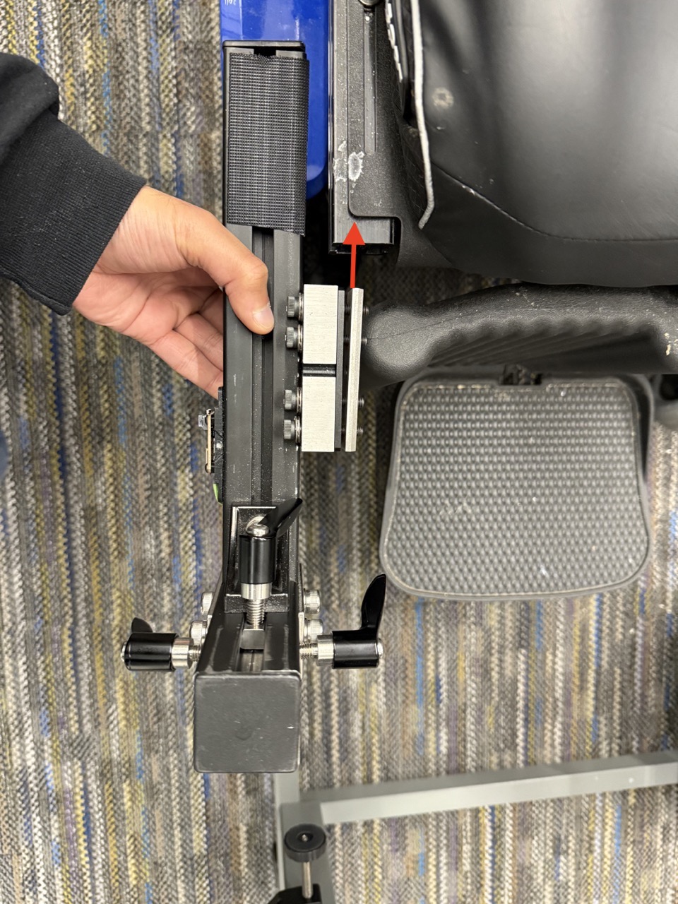
Once the wheelchair mount is assembled (see images), you can slide the linear connector into the wheelchair's sliding track, and attach the robot arm to the mount using the clamping lever ratcheted screws.
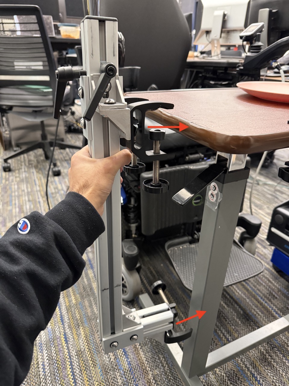
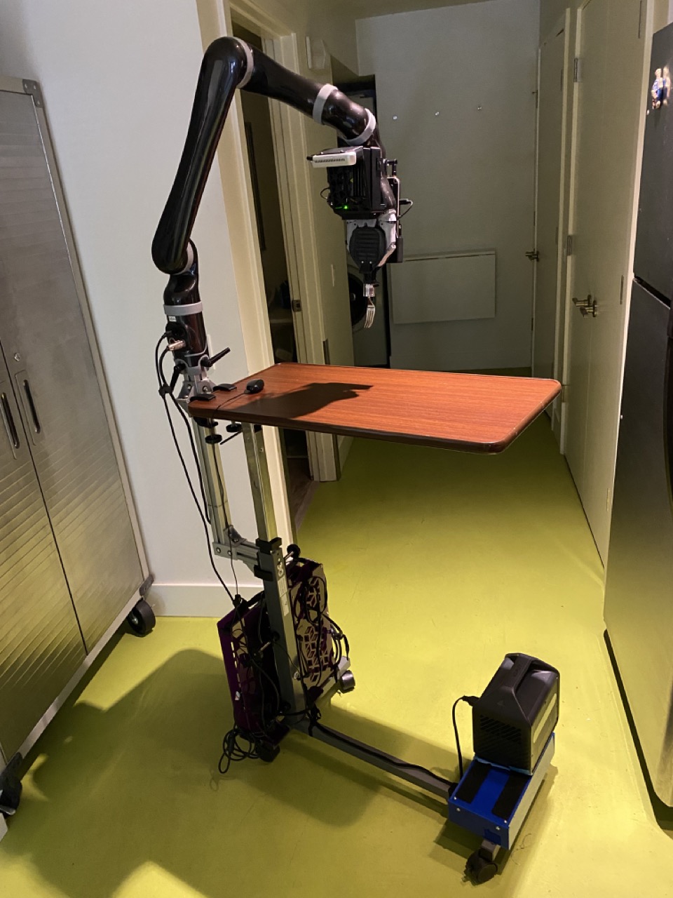
4.1.2 Hospital Table Mount
For meals when users aren't seated in their wheelchair, it can be helpful to have a mount that can be wheeled to wherever the user is. Hospital tables are commonly used as part of care routines because they are wheeled, height-adjustable, and lightweight. Thus, we developed a robot mount that can be clamped onto a hospital table, to accomodate out-of-wheelchair meals (e.g., in-bed meals). This mount consists of the following parts (labeled in the images):
- A 55cm piece of 40-40 (although we joined two pieces together for this length, a single piece is preferrable)
- A 10.6cm piece of 40-40 (depending on the distance from the edge to the post of the hospital table)
- Three clamps to connect the 40-40 and hospital table
- Three 40-40 end caps
- Three clamping lever ratcheted screws
- Two joining plates, five corner bracket, and associated M8 screws and nuts
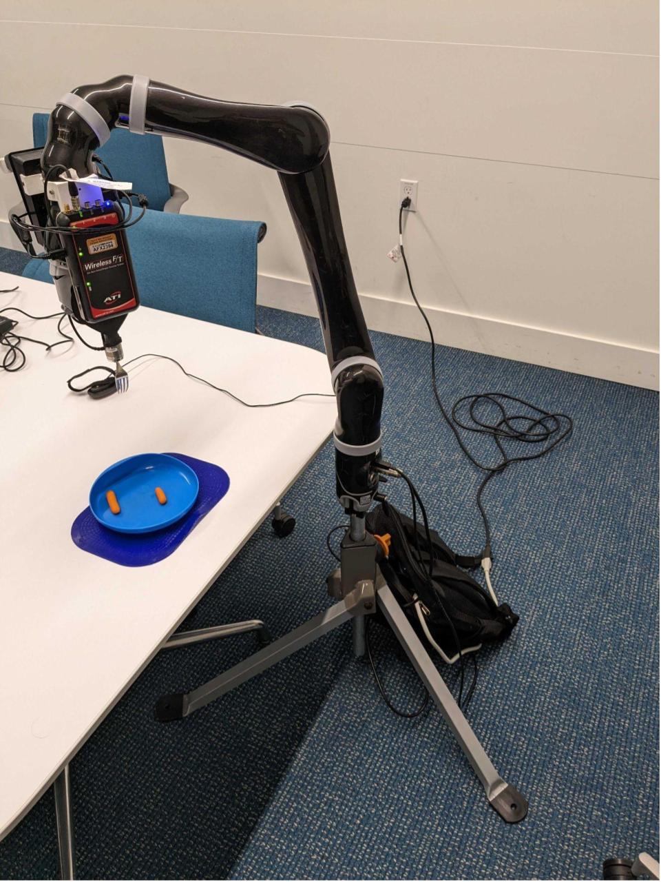
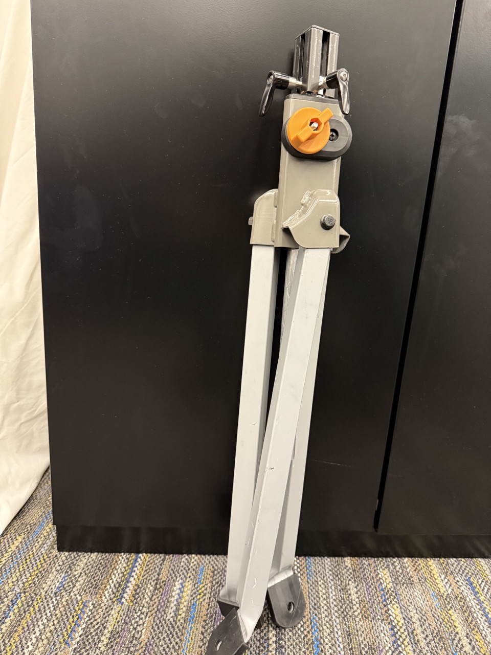
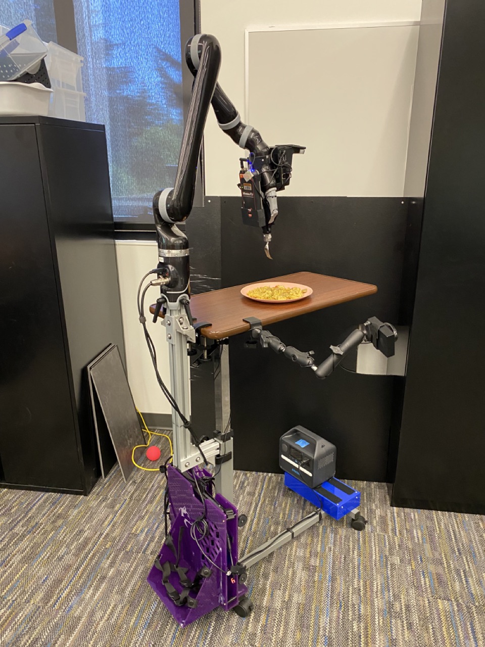
4.1.3 Tripod Mount
Sometimes, it can help to have additional flexibility in where one sets up the robot. For such scenarios, we use a tripod mount. This mount consists of a Rockwell RK9033 tripod, with 40-40 welded onto the adjustable center rod. A tripod mount is a great fallback for studies where time or spatial constraints make it challenging to use the other two mounts.
4.1.4 Mounting the E-Stop Button
Regardless of which of the aforementioned mounts we use for the robot, the emergency stop (e-stop) button must be mounted in an accessible location for the user to press. We typically use RAM mounts for this purpose, as they are commonly used to attach and adjust the position of accessories on power wheelchairs.
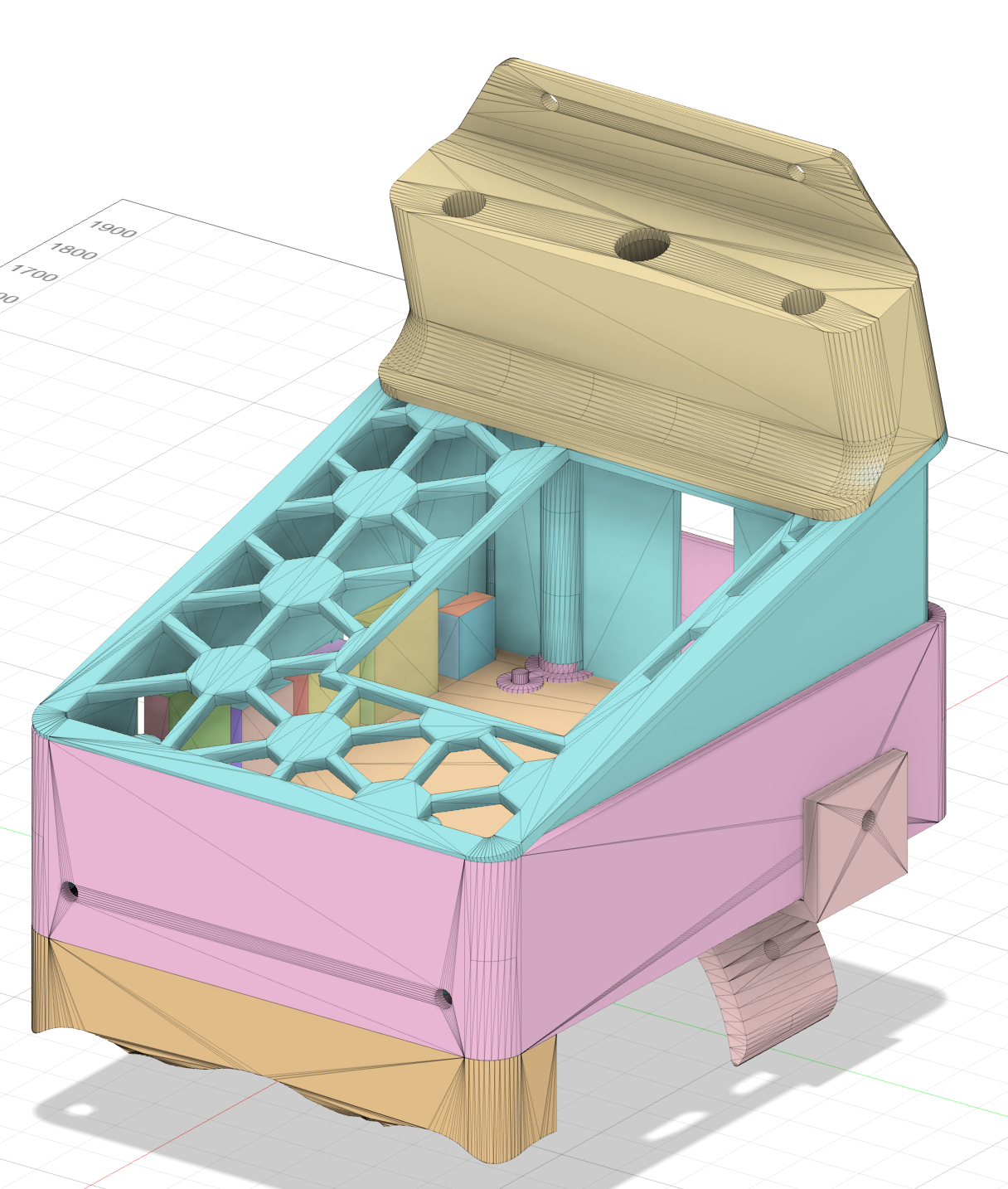
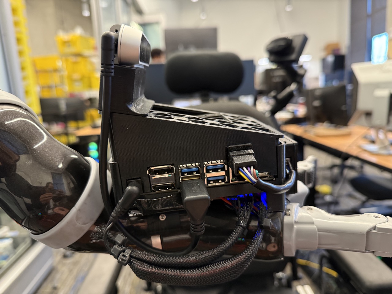
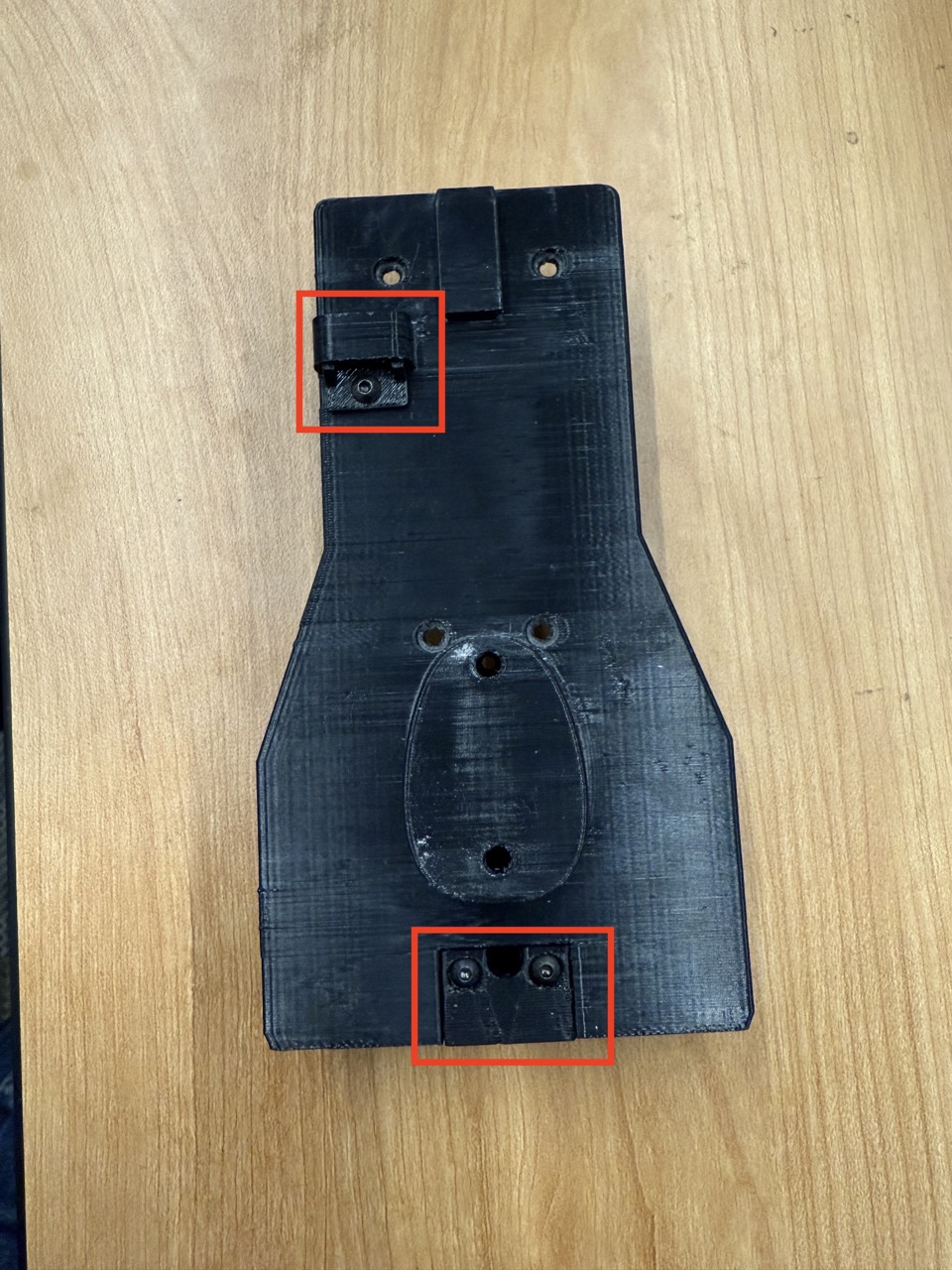
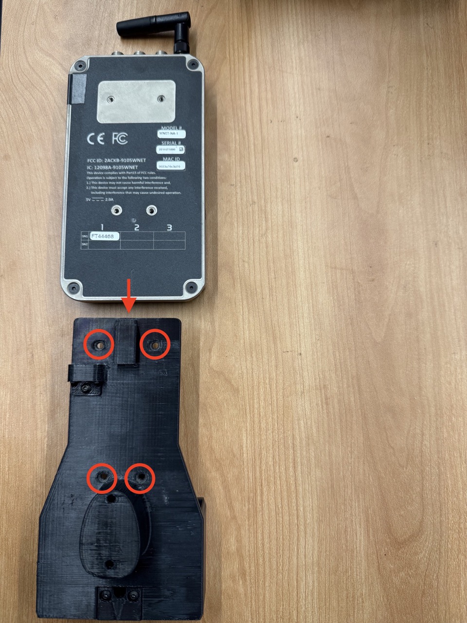
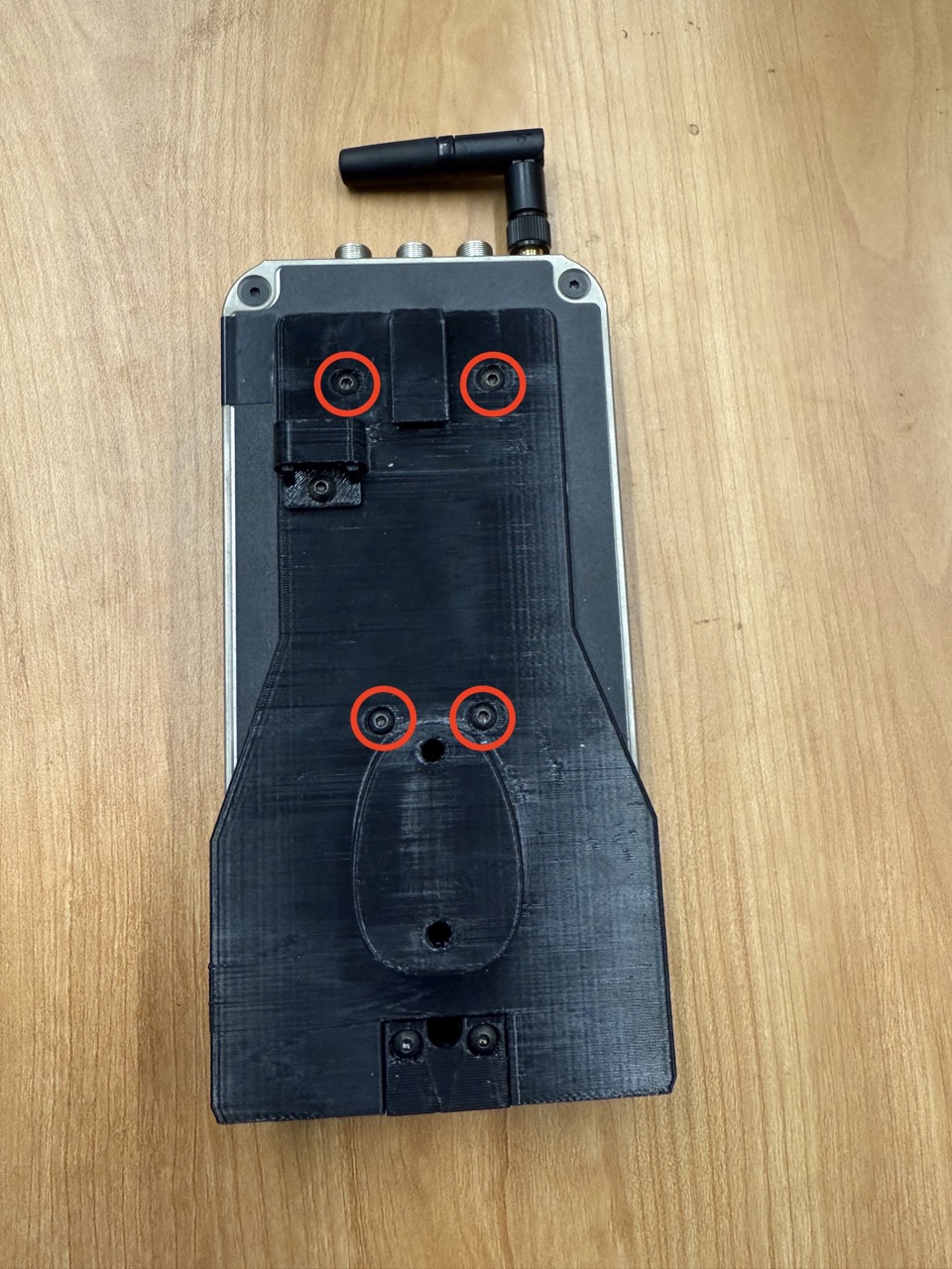
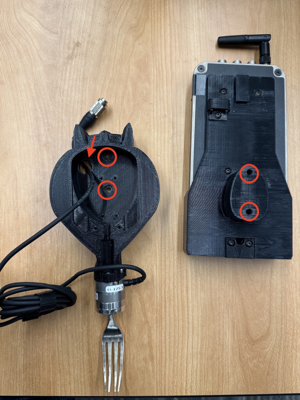
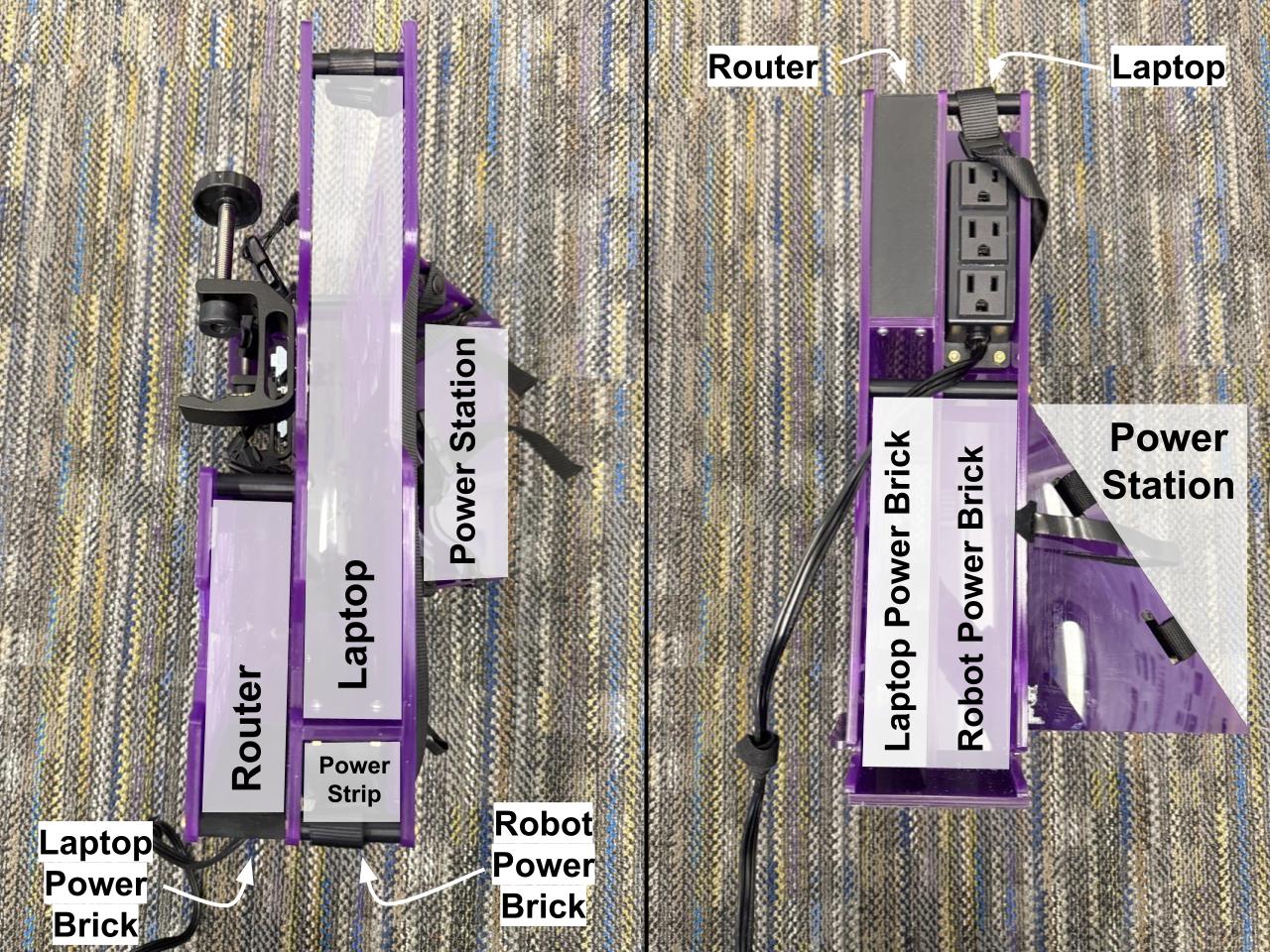
4.2 Electronics Mount
The electronics mount is made out of 1/4th inch thick acrylic sheets, which we laser-cut and glued together (using acrylic glue). This mount is designed to hold all the electronics of the system. It always holds the system's laptop, and depending on the use case, can optionally hold a router, a power station, and the power bricks associated with the laptop and robot's power supplies. This electronics mount is designed for use with various of the robot mounts above. For example, when the robot is mounted onto the wheelchair, the electronics mount can be hung from hooks on the back of the wheelchair. When the robot is mounted onto a hospital table, the electronics mount can be clamped onto the base of the hospital table, with the portable power station on the other side.
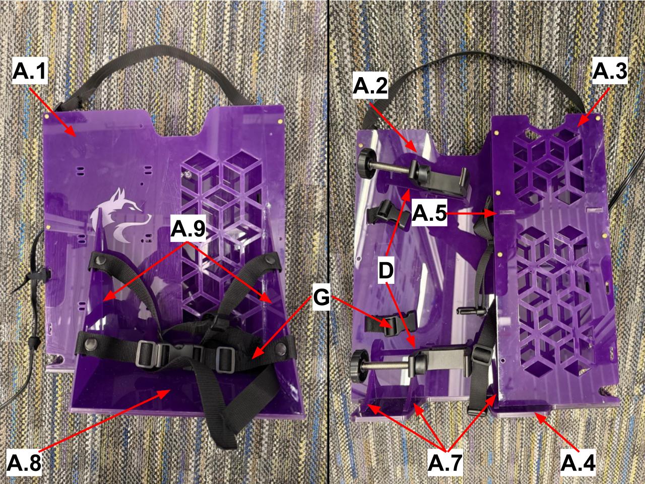
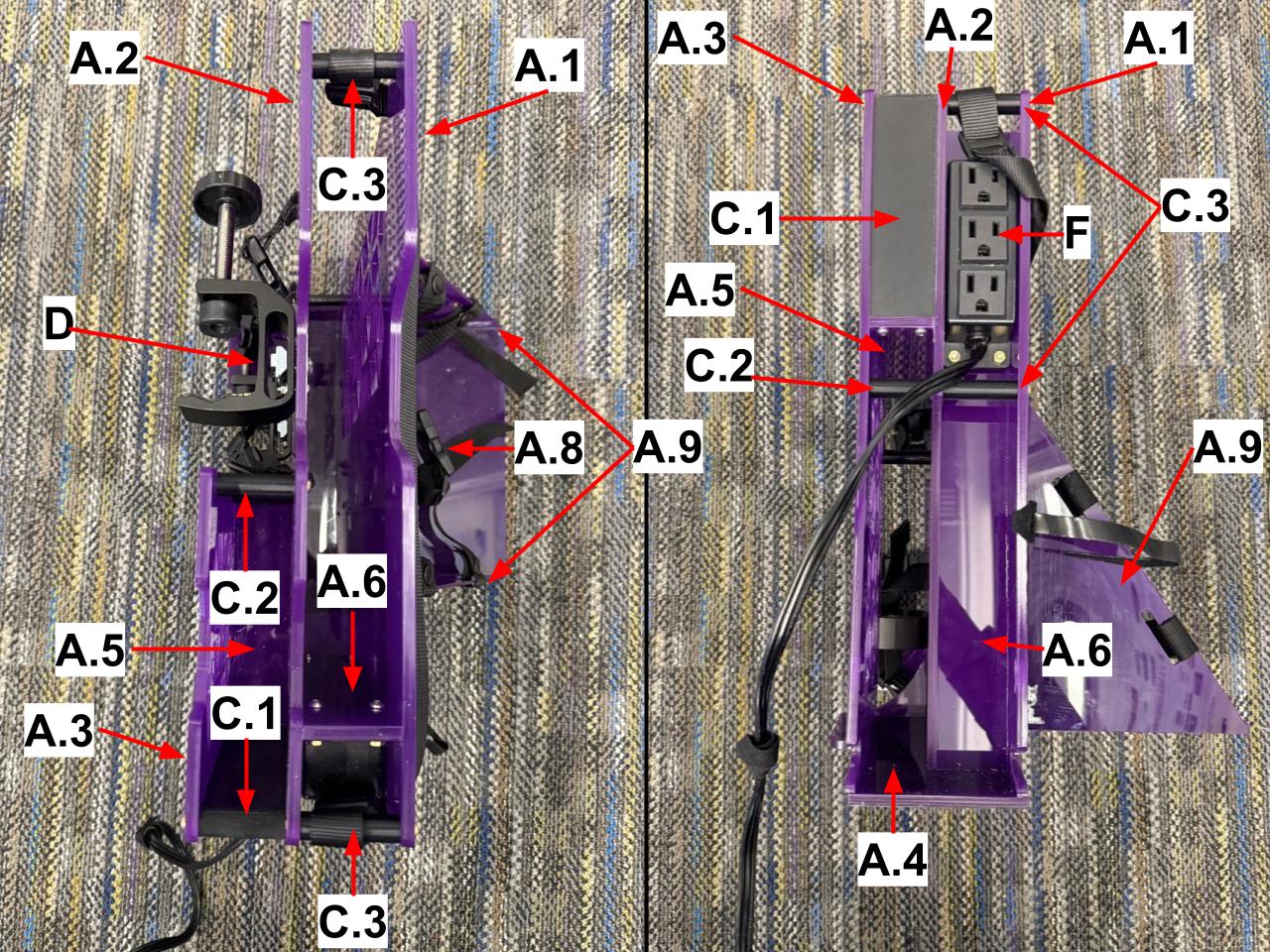
The electronics mount consists of the following parts (labeled in the images):
- Laser-cut acrylic:
- Acrylic glue
- 3D-printed supports (PLA):
- Clamps (2) and corresponding M8 screws and nuts
- Assorted M4 screws, nuts, and thread spacers. The thread spacers are inserted into the "screw supports" mentioned above.
- One power strip
- Buckle straps and snap fasteners, velcro
- Grip tape

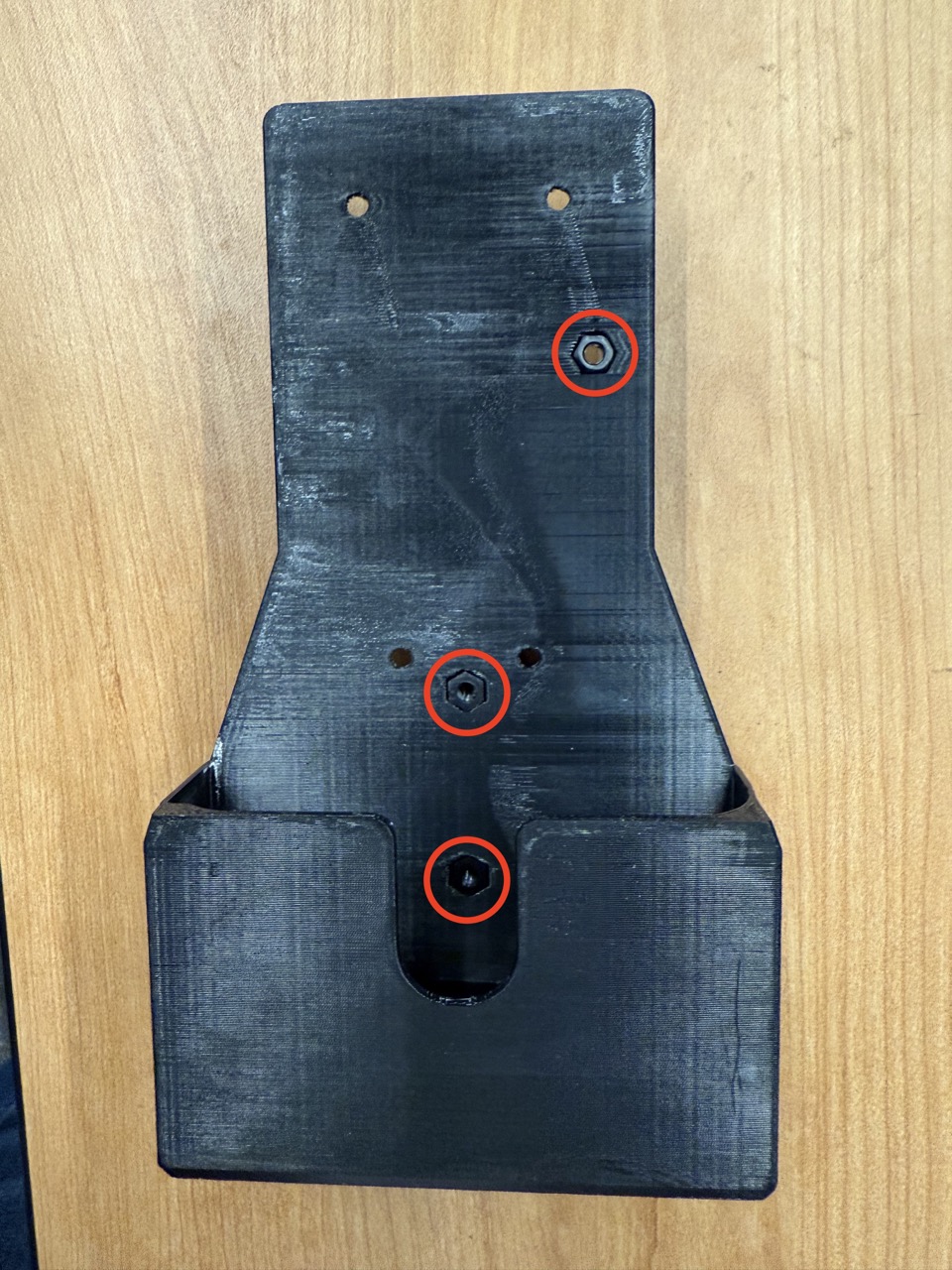
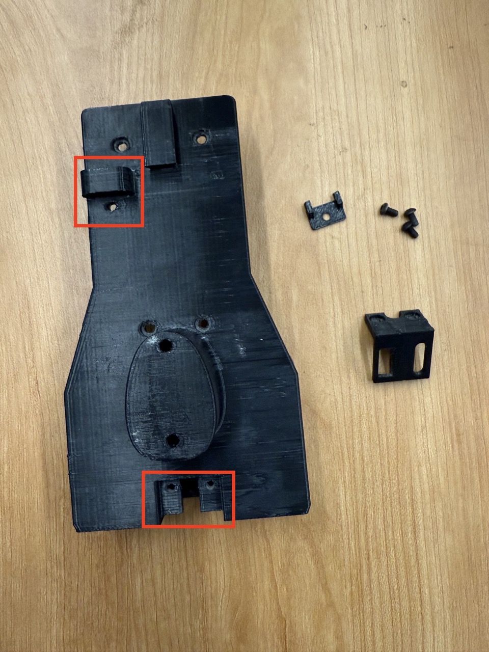
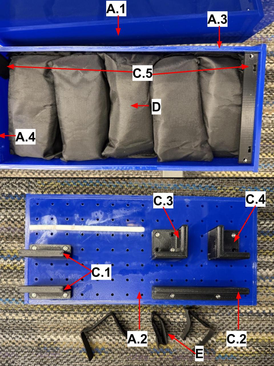
When attached to the hospital table mount, the robot arm and the electronics mount place disproportionate weight on one side of the table. To counteract this, we developed a counterweight, that consists of the below parts. Use acrylic glue to attach the bottom and side plates, screwn the hospital table aligners onto the bottom plate, screw the lid bracket into the inside of the side plates, place the weights inside, and screw the top plate on. Place the assembled counterweight over the hospital table legs, slide velcro through the slots in the hospital table aligners, and velcro it on.
-
Laser-cut
acrylic:
- Top Plate (1)
- Bottom Plate (1)
- Long Side Plate (2)
- Short Side Plate (2)
- Acrylic glue
- 3D-printed supports (PLA):
- 10lb ankle weights (2)
- M4 screws and nuts.
- Velcro
5. System Power
Several system components need power. There are three options for that power: (a) from the power wheelchair, (b) from a portable power station, or (c) from a wall outlet.
5.1 Power Wheelchair Power
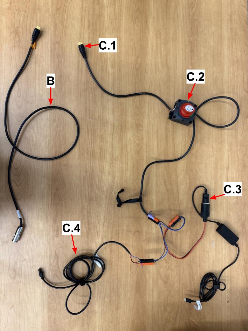
Power wheelchairs typically have a specific (and sometimes proprietary) type of outlet that can be used to power accessories. Like with any other outlet type, there tends to be an ecosystem of extension cables, splitters, and more for the wheelchair's outlet type. Such accessories can taken from old wheelchairs, purchased from the manufacturer, or purchased from used parts stores like Liberty Mobility. Specifically, to power the system from our particular power wheelchair (24V), we use:
- A multi-link connector to provide more outlets
- A cable to deliver power to the robot, procured from Kinova and its distributors.
- Powering the laptop and router:
Note that developing the adapter to power the laptop and router from the wheelchair involved cutting some cables and soldering wires to the appropriate connectors. As such, developing the adapter requires some familiariaty with electrical engineering and appropriate safety precautions.
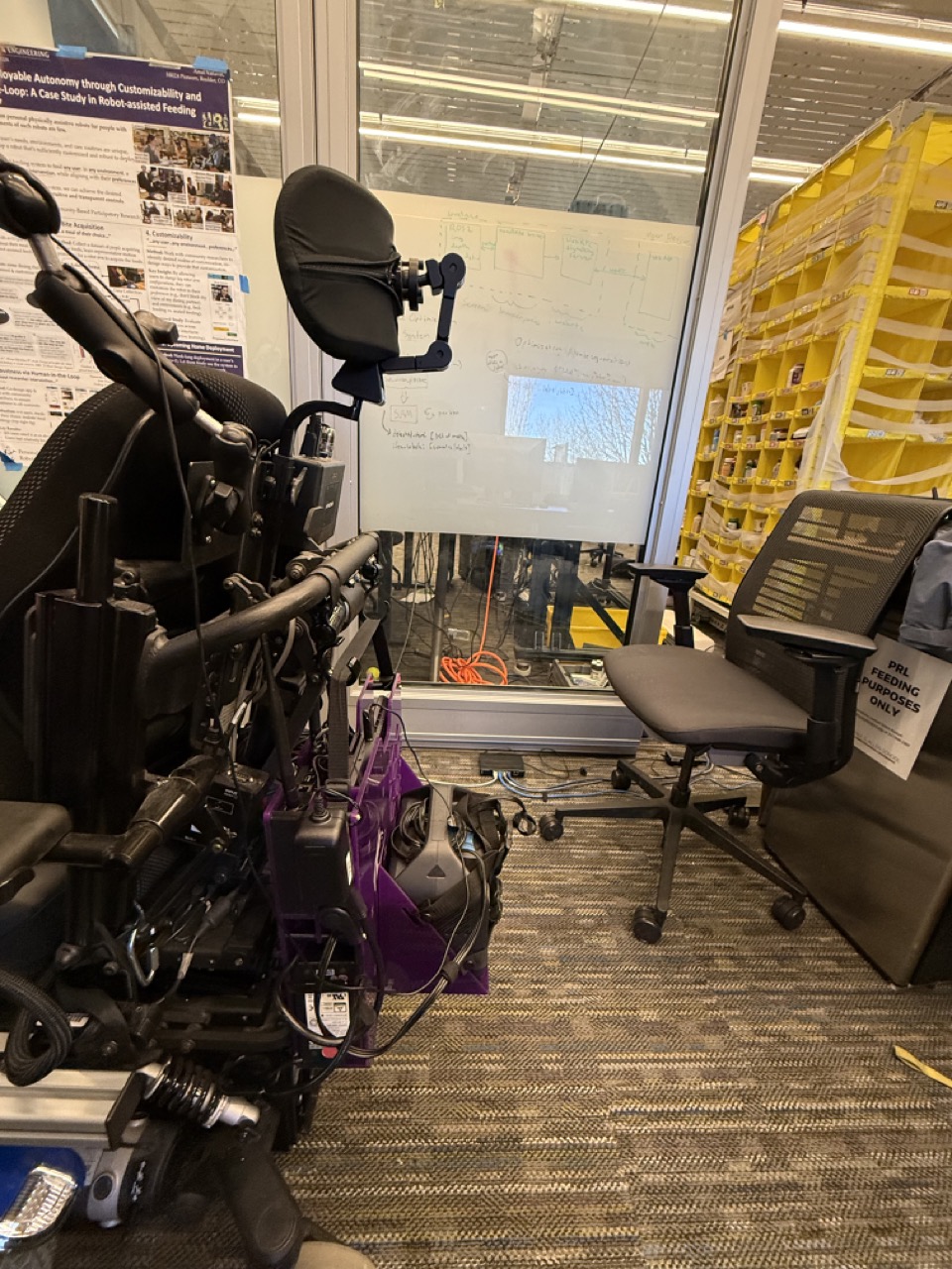
5.2 Portable Power Station or Wall Power
The electronics can alternatively be powered by wall power, or alternatively by a portable power station that provides sufficient wattage. Both these options use a 3-pronged plug (U.S.) standard for power, which is screwed into the electronics mount. The pictures show the power station powering the system on the wheelchair (useful if one hasn't created the adapter for that specific wheelchair's outlet) and on the hospital table. If need be, the same plug that inserts into the power station can be plugged into wall power, although that does reduce system portability.
5.3 Powering the Robot's Wrist Attachments
We power the eye-in-hand system through the robot's internal 12V power BUS. Because the Jaco® arm is designed for two or three fingers, the final link has power wires for up to three fingers. Since our system only uses two fingers, we draw power from the third finger's power wires, using a step-down voltage regulator to get the 5V necessary for the eye-in-hand system and the wireless F/T transmitter. Note that the process of redirecting power intended for one use to another use can be risky. Thus, we intentionally do not include detailed instructions here. Instead, we recommend consulting with the manufacturers of your robot arm and with electrical safety experts before attempting to draw power from the robot arm to power additional attachments.
The wireless F/T transmitter requires micro-USB power. We provide that power from the Jetson Nano. One option is to directly connect a cable between them. However, this prevents the robot arm from being able to let go of the fork (since the fork assembly can be let go of, but the eye-in-hand system cannot). Instead, we use magnetic connectors to establish the connection between the Jetson Nano's USB port and the wireless F/T transmitter's micro-USB port. Thus, there is a connection when the robot is holding the fork, but the connection is broken when the robot lets go of the fork.